Measurements are necessary (it are a must) in electronics. Nothing it could work without. There is a very big difference in measuring a stage, or few connected, for appreciations on quality or for faults finding. We have methods, algorithms, tools and so on for such measurements. A completely different task is to measure a whole system to appreciate its overall quality. This is almost impossible. The measurements trials who one or another may be doing, it (can)not target the whole device as a system, but it target parts of the system (audio, video, THD, noise floor, etc. etc). Using these singular measurements results, one try appreciating how good the whole device/system it may be. This is a grove approximation, which mean almost nothing in conjunction with the human perceptions, its subjectivity or very different criteria for appreciations. So what`s the point here?
Measuring and analysing a whole system quality, it need a enormous preparing work, establishing the scientifically methods, the use of right tools, establishing the methods for result interpretations, and so on. Such work it could take years for a team, and in the end it still be not sure if they did it right, or the results of what they have measured it reflect the real world (perceived by humans and their more or less precise and strongly subjective criteria for appreciations).
Who have the time, energy and founds to do such work? And for what purpose? Only for giving satisfactions to one or another, who may throw out at once the piece of paper, just after reading the results, and then powering up their (preferred for years) audio/video system for listening or film watching... Who really care about such?
On other hand, one can very well understand the needs for objective criteria for appreciations of different statements, we are flooded by the informational system world wide and in all fields. However, not everything it can be measured or put it into strict flow charts, algorithms, and so on. The best way of doing it still be the human appreciation (using own algorithms), which every individual may poses (more or less). Then exchanging that appreciations/impressions with other individuals/peoples it is another way for revealing a kind of overall result... Which it will never be a precise one.
Last edited:
Yup. I like measurements too. Perhaps it's the human need for some kind of foundational reassurance.
Yet I know ordinary stuff can measure almost as well as the good stuff and don't say nuthin' about how it will sound.
Anyways, the fun for modding and for audiophile is in the pursuit! And the delightful music!
Yet I know ordinary stuff can measure almost as well as the good stuff and don't say nuthin' about how it will sound.
Anyways, the fun for modding and for audiophile is in the pursuit! And the delightful music!
Here’s another set of measurements and it’s simular to what Amirm’s results:
Archimago's Musings: MEASUREMENTS: Oppo UDP-205 Part 1: Output levels and digital filter settings... (And a few words about recent Munich 2018 MQA interview videos, McGill listening test out.)
This is another 3 part measurement of the OPPO 205. The 105 is also on there.
Those critical of Amirm’s measurements questioning his methods and results should ask themselves if they have a $25k-29k AP555, just to measure a $2200AUD stock 205.
I’m not critical in some of the mods here, it’s extremely entertaining while I watch on the fence line. But I’d like to see b4 and after measurements on the effect the mods might have on the stock unit and hownit effects SQ to the ears. Then again it’s all subjective isn’t?
I’ve seen the 105 measurements on several different sites and they all measure well for the $$$$. However I’ve never compared a modded 105 to a stock standard so I can’t comment. But what I will comment is everytime I replace a component whether it be a capacitor, opamp etc there is a difference to the SQ presentation.
Measurements are necessary (it are a must)...
Absolutely!
It will show rubbish for what it is: Rubbish!
Bad engineering for what it is: Bad engineering!
But at some point, forget about the measurement and just listen.
But we can enjoy both, right. Just maybe, not always at the same time.
")
Absolutely!
It will show rubbish for what it is: Rubbish!
Bad engineering for what it is: Bad engineering!
But at some point, forget about the measurement and just listen.
But we can enjoy both, right. Just maybe, not always at the same time.
Which is why I appreciate the work by people like Sean Olive who use measurements as what they are, tools, along with *education* and training, in order to correlate the perceived with the measured. That takes time, resources, and money.
Of course it helps that he has multi million dollar facilities to conduct testing...
Such ********. Oh, we all hear differently...crap!!!. However you hear, what you hear, is how you perceive reality. It doesn't matter that Bob's hearing 'measures' differently from John's. They both grew up with what they have. So their perception of transparency as regards reality/the gear is identical. How close to reality(their realities) is it? Put a stock one against a modded one. Simple. As enough people to compare to their own sense of reality and you'll arrive at consensus. Done.
This is the 1st time I’ve seen a real measure on a stock vs modded for a OPPO device and in this case the 105. Here we have one where the mods are possible more than the 105 itself.
The data speaks for themselves.
Archimago's Musings: MUSINGS: Thoughts on audio device "modding" (eg. a tube modded Oppo BDP-105). [New Oppo UDP-205 firmware out with MQA USB-B...]
The data speaks for themselves.
Archimago's Musings: MUSINGS: Thoughts on audio device "modding" (eg. a tube modded Oppo BDP-105). [New Oppo UDP-205 firmware out with MQA USB-B...]
Opening the can was a bitch!!
How did you do it, I can imagine is was not easy, so what 'technique' did you use?
.
Last edited:
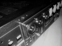
I wonder also how they may doing it when soldering the can on board... It seems to me that all soldering points of the can are soldered simultaneous... I have used a 100w soldering iron and I couldn`t remove it. It is a such big heat spreading on that ground plane, and the risks for damages on board are very high (as to be seen in the above picture also...).
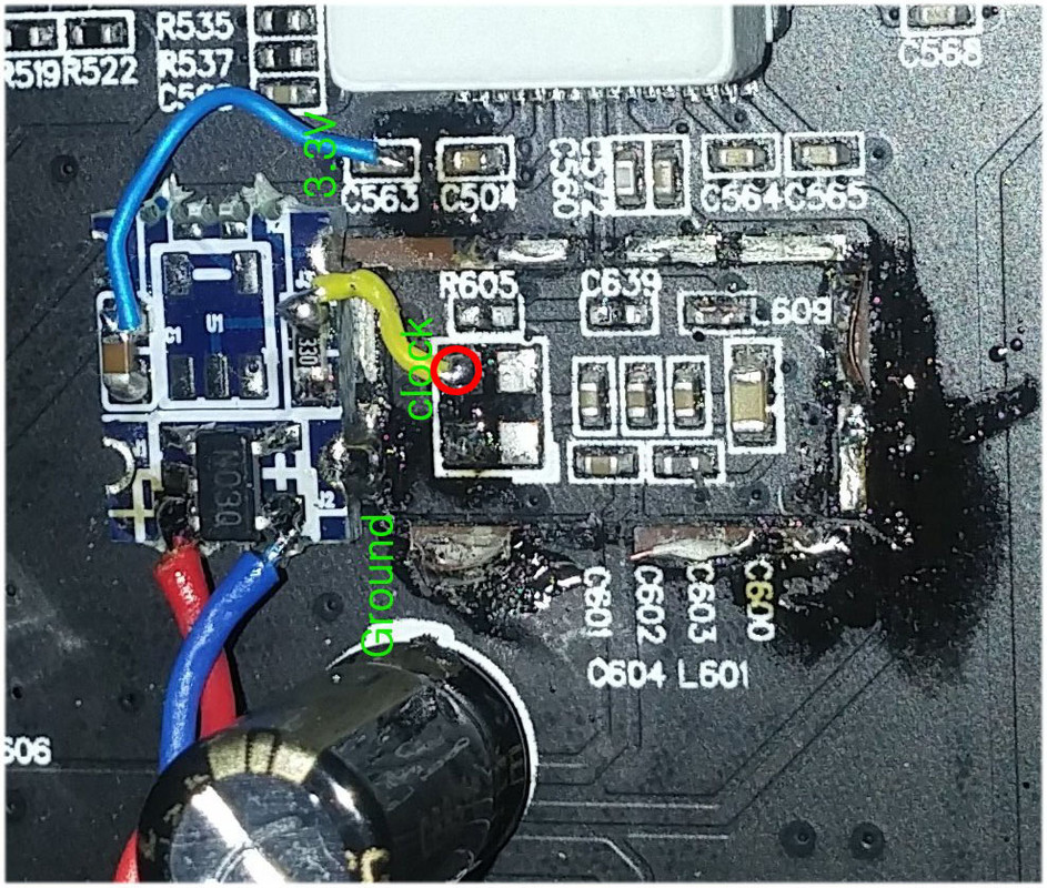
However, I repeat my opinion that the can removing is absolutely unnecessary (now when we know what is inside). Here I can see only two alternatives: either using the circuit as it is, or cutting the clock out trace, and power rail to the original circuit, and then inserting the new clock circuit/signal. At least the can itself so as it is soldered on board, is a very good support for a UFL connector (my solution) or another small PCB, as the one used in the above pictured case...
However, I repeat my opinion that the can removing is absolutely unnecessary (now when we know what is inside). Here I can see only two alternatives: either using the circuit as it is, or cutting the clock out trace, and power rail to the original circuit, and then inserting the new clock circuit/signal. At least the can itself so as it is soldered on board, is a very good support for a UFL connector (my solution) or another small PCB, as the one used in the above pictured case...
Attachments
Last edited:
How did you do it, I can imagine is was not easy, so what 'technique' did you use?
.
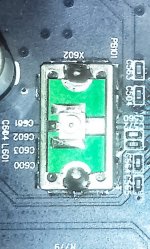
We tried almost all technique and almost give up then we cut the metal housing with cutter. Destroy it bit by bit once get into small pieces very easy to take off from PCB.
Cut the corner first then go around.
Here’s another set of measurements and it’s simular to what Amirm’s results:
Archimago's Musings: MEASUREMENTS: Oppo UDP-205 Part 1: Output levels and digital filter settings... (And a few words about recent Munich 2018 MQA interview videos, McGill listening test out.)
This is another 3 part measurement of the OPPO 205. The 105 is also on there.
Those critical of Amirm’s measurements questioning his methods and results should ask themselves if they have a $25k-29k AP555, just to measure a $2200AUD stock 205.
I’m not critical in some of the mods here, it’s extremely entertaining while I watch on the fence line. But I’d like to see b4 and after measurements on the effect the mods might have on the stock unit and hownit effects SQ to the ears. Then again it’s all subjective isn’t?
I’ve seen the 105 measurements on several different sites and they all measure well for the $$$$. However I’ve never compared a modded 105 to a stock standard so I can’t comment. But what I will comment is everytime I replace a component whether it be a capacitor, opamp etc there is a difference to the SQ presentation.
I dont know bout this measurement but I can tell my 205's MOD is wayyyyyy wayyy much better than the original one.
I dont know bout this measurement but I can tell my 205's MOD is wayyyyyy wayyy much better than the original one.
Hey sandtodx5
What are the various mods you made?
I shall post some impressions of my mods soon. Takes a bit longer as I wanted to do the changes in a few steps, burn-in and listen before moving to the next step.
Denis
Hey sandtodx5
What are the various mods you made?
I shall post some impressions of my mods soon. Takes a bit longer as I wanted to do the changes in a few steps, burn-in and listen before moving to the next step.
Denis
I had LPM, new master clock and 100hz clock in analog board, IEC NCF with solid core cable, all caps + resistors +regulators + xlr connectors in analog board are replaced. There is no comparison before and after, I don't even like the sound unmodified, dull and pale!
I had LPM, new master clock and 100hz clock in analog board, IEC NCF with solid core cable, all caps + resistors +regulators + xlr connectors in analog board are replaced. There is no comparison before and after, I don't even like the sound unmodified, dull and pale!
Wow. Do you have a sense of the relative impact of the bigger items? If you were to rank them 1. In terms of sound impact and 2. In terms of cost, how would the mod items stand?
For me, replacing the LPM is foundational - sets the basis for a completely quiet and more dynamic background for both video and audio.
Supplying linear power to the digital inputs section elevated HDMI music (from smart TV via Audio Return Channel) and ethernet sourced audio and video very much. I would say music from my NAS is now much improved.
Surprising, changing the stereo board +/- rail regulators with ultralow noise TPS7A set yielded amazing improvement to the sound - much more analogue like and "you are there". A must do for relatively cheap cost ~$25.
Yes indeed, there is an audible clicking when DSD signal is detected. I haven`t analysed in deep this event, but my in interpretation is that it is about a short time mute relays activating to prevent eventually high level audible noises on outputs, while switching to/from DSD mode. There is not about a power cycling for the whole analogue stage.
Well, Amir actually has a very extensive tech background in both breadth and depth.
...
This engineer begs to differ. His background is QA. After spending 15 years in the RF industry, QA types seem to be sky-is-falling types more often than not. He basically got a golden parachute from MS and appears to have a bone to pick with Schiit (whose veil has been lifted, rightly or wrongly).
UDP-205 and a Schottky Bridge?
I recently sold my BDP-105 and bought a second hand UDP-205. In my 105 I changed the SMPS for a Coris-LPS, bridged the output C's and changed the diodes of the analog supply to MUR860 Schottky's. After a week listening I now can say that the sound of the 205 right out of the box is quite a bit worse than the modded 105. So I have to mod!
Before buying a new LPS (I have to start again with savings), I measured the outputs and bridged the output C's. Sound (XLR) is a bit better but not on the level I was used to of course. Now I am starting with the rectifier(s) of the stereo board. In the 205 they are now using 3 bridges (Vishay DF02S). Is there anybody who changed these bridges for a Schottky bridge? Could the PanJit TS2100S be an altenative? If this is possible, I think this is a more elegant solution than a construction with 4 diodes.
I recently sold my BDP-105 and bought a second hand UDP-205. In my 105 I changed the SMPS for a Coris-LPS, bridged the output C's and changed the diodes of the analog supply to MUR860 Schottky's. After a week listening I now can say that the sound of the 205 right out of the box is quite a bit worse than the modded 105. So I have to mod!
Before buying a new LPS (I have to start again with savings
), I measured the outputs and bridged the output C's. Sound (XLR) is a bit better but not on the level I was used to of course. Now I am starting with the rectifier(s) of the stereo board. In the 205 they are now using 3 bridges (Vishay DF02S). Is there anybody who changed these bridges for a Schottky bridge? Could the PanJit TS2100S be an altenative? If this is possible, I think this is a more elegant solution than a construction with 4 diodes.The advantage of using stand alone Schottky diodes for a rectifier bridge, instead of compact made bridges, is that one can select the best (lowest) forward voltage diodes. One should know also that as the max current increase (in specifications), the Forward Voltage parameter it decrease. For physical dimensions reasons, one can not just use many teens A diodes. A good compromise in between dimensions, max current, and forward voltage it should be possible by using individual diodes.
Using compact bridges is a convenient and elegant solution. Not always the best one...
The first selection criteria (except the max supported forward current), is a lowest as possible forward voltage. The biggest advantage of Schottky diodes is in case of rectifying 50/60Hz voltages, not its switching speed (for a such low frequency), but is its forward voltage, which it can be very much lower than the standard rectifying diodes. The FV of TS2100S is huge, and there is no any differences than a standard low cost rectifying bridge (when rectifying 50/60Hz)... I wouldn`t use myself a such bridge in the mentioned place (if improvement is the target).
Last edited:
- Home
- Source & Line
- Digital Source
- Oppo new UDP series players - 203/205 - Discussions, upgrades, modifications