Please ignore previous link - I meant this one:
http://www.vishaypg.com/docs/63140/var.pdf
Although I think these in principle should improve the signal path, but my main aim is to improve sound image....
http://www.vishaypg.com/docs/63140/var.pdf
Although I think these in principle should improve the signal path, but my main aim is to improve sound image....
The resistors quality it is important of course, but in case of Oppo players improving the sound quality, it may not strictly refer to the improved resistors quality on boards. Definitely not in the first instance... At least replacing all the resistors in audio section with these ones, it could be quite expensive and an enough tremendous work.
The main direction for improved quality for both sound and picture, are the improvements on power systems (digital and analogue stages). Another big impact over the quality parameters, it is made by improvements for clock system.
Experimenting with these mentioned resistors it may be the very last step, after everything else is already improved inside these devices...
Last edited:
Different resistor types can make a significant difference in the direct analog audio signal path or feedback loops, in many cases as much difference as capacitors can provide.
Although I have not made any changes to my UDP-205 yet, I have tried these film or foil resistors in various pieces of equipment (both digital and analog gear) and all vary greatly in sound quality:
- Dale
- Roederstein Resista / Draloric
- PRP
- Holco
- Caddock MK-132
- Takman
- Audio Note Tantalum regular & non-magnetic
- Shinkoh Tantalum
- Caddock TF020
- Vishay/Sfernice S-foil types with coatings (VSH, VTA, RCK, RNC, S102 series)
- Vishay "nude" S-foils (aka TX-2352)
- Vishay "nude" Z-foils (aka VAR and TX-2575)
The list is just an approximation of quality as much finer delineations can be made. As an approximation, the later in the list the better the sound quality. I find the Vishay foil resistor types to have greater clarity and openness of sound stage compared to all the other types.
I have finally gotten my hands on a '203 and looking inside it right now. I have figured out what I want to do with it, i will do the 27mHz clock using divided 54MHz SAW (how long ago was it that I fingered SAW oscillators, time sure goes fast), then that 27mHz clock signal will go through an analog clock buffer (yes, it makes quite a difference). I will do some power supply enhancements in and around the AKM4458 DAC, then on the output phases use two 1:1 transformers going to separate floating RCA sockets on the back panel (with the right cable, this means balanced output is possible, floating RCA to XLR). The Zobel network on the transformers will be carefully tailored to give near 0.5dB down @ 10KHz and 1.5dB down at 20KHz, forming an infamous 1st order post-DAC filter.
I won't be using any linear power supply, there will be no active post-DAC circuitry, so less need. Also, I want to keep the costs down, but without any compromise to the sound. I think this will work just fine.
.
I won't be using any linear power supply, there will be no active post-DAC circuitry, so less need. Also, I want to keep the costs down, but without any compromise to the sound. I think this will work just fine.
.
Hi Ludvik
Indeed the both picture and sound quality are improved when replacing the original clock system for both 203/205 models. This in conjunction with also using a linear power supply. The positive impact over picture is more noticeable actually on 205. I suppose the main processor on 205 models is of a newer version, than the one in 203. The clock board is also ready to clock the stereo DAC as well for 205.
Indeed the both picture and sound quality are improved when replacing the original clock system for both 203/205 models. This in conjunction with also using a linear power supply. The positive impact over picture is more noticeable actually on 205. I suppose the main processor on 205 models is of a newer version, than the one in 203. The clock board is also ready to clock the stereo DAC as well for 205.
Last edited:
Ok.thanks.
-Is the clock/or clocks on the mod-board of high quality, is there more to gain from "higher grade" clocks/femtosecond ?
-Can you tell me some info about the battery used on the clock board.
Do you know how many time it can be charged(the quality of the battery) ? And is it possible you can run out of battery-power when the player is in use ?
The clock system on my clock board for 205, it use a master Epson SAW oscillator of 108Mhz. The output of this oscillator is directly available for clocking the stereo DAC. The same frequency is divided to 27Mhz for the main processor and the HDMI dedicated audio chip. A precision TXCO of 25Mhz oscillator it clock the optical drive decoder/processor.
All the oscillators on board are directly powered from the battery (mobile phone rechargeable type), as the ground connection is disconnected from anything else but the oscillators and battery, at powered on.
The battery is removable, and it can be replaced if it may fail in the same maner as for a mobile phone. As the oscillators on board it use very smal amount of the battery energy, this is very little solicited for this function. Also the charging current is much less than in a usual phone. The life of the battery is so very much extended, and it can be used for years on this board. The battery is always charged to full while the device is off. A fully charged battery it can continuous run the oscillators for more than 12 hours, without any fault. This functional time range is very large and is out of the usual use for a such player. However, if the battery it get discharged under the oscillators safe functioning level, then the whole device it stop functioning, and it allow only power off command. After charging, everything it works as before. A 10 min charging it allow more than 2 hour functioning for the player.
Last edited:
The OPPO 205 has a main clock of 27 MHz as system clock and a 100 MHz clock on the DAC board.
Of these two clocks, 27MHz femto clock has already been used in Oppo 203 to confirm the correctness of the waveform
This time, I compared waveforms before and after tweak of 100Mhz clock.

It is waveform by original clock before tweak. considerable amount of Jitter (indicated by a square) is shown

In the photo of after tweak. It shows that there is practically no Jitter and wave shape is almost perfect retangular.
After tweak. It shows a distinct sound quality difference even when it is not yet fully aged.
With the Linear Power supply, the bass sounds more like one octave deeper. The surprise is the bass accuracy.
In addition, the sound and position of each musical instrument shows exact and outstanding performance. Digital sources, especially DSD files and high-resolution PCM files, made a big difference.
Especially, the higher the frequency, the harder it is to get the correct waveform,.
But thanks to the buffer circuit is placed in front of each clock input, it can be transmitted with maintaining accurate waveform.

(buffer circit)

( femto clocks,2 seperate frequencies are possible)
For reference, this is a waveform of 25 MHz (for BD ROM Drive)
The system clock, 27 Mhz, is on the bottom of the board, which is difficult to measure and shows a similar 25 Mhz waveform.

( orignal circuit's wave form and jitter of 25

after Femto clock upgrade
Of these two clocks, 27MHz femto clock has already been used in Oppo 203 to confirm the correctness of the waveform
This time, I compared waveforms before and after tweak of 100Mhz clock.
It is waveform by original clock before tweak. considerable amount of Jitter (indicated by a square) is shown
In the photo of after tweak. It shows that there is practically no Jitter and wave shape is almost perfect retangular.
After tweak. It shows a distinct sound quality difference even when it is not yet fully aged.
With the Linear Power supply, the bass sounds more like one octave deeper. The surprise is the bass accuracy.
In addition, the sound and position of each musical instrument shows exact and outstanding performance. Digital sources, especially DSD files and high-resolution PCM files, made a big difference.
Especially, the higher the frequency, the harder it is to get the correct waveform,.
But thanks to the buffer circuit is placed in front of each clock input, it can be transmitted with maintaining accurate waveform.
(buffer circit)
( femto clocks,2 seperate frequencies are possible)
For reference, this is a waveform of 25 MHz (for BD ROM Drive)
The system clock, 27 Mhz, is on the bottom of the board, which is difficult to measure and shows a similar 25 Mhz waveform.
( orignal circuit's wave form and jitter of 25
after Femto clock upgrade
Last edited:
Looking at the screenshots of your measurements of the original clock signals (100Mhz and 25Mhz), I can observe that the stated original clock signal of 100Mhz is enough distorted (first picture). I have scope it myself this signal and I found a very nice sinusoidal signal (out from original oscillator)...
The first measurement illustration of the 100Mhz distorted sinus (coming from a oscillator device), it shows only few so called jitter indicators, while the quite perfect sinusoidal signal of the 25Mhz clock (produced by a resonator), it shows in your illustrations, lat of such stated jitter indicators (big amount jitter).
I may say that I found quite strange all about these aspects .
Some questions:
Knowing that a sinusoidal shaped signal is much closer to a pure and unprocessed signal, and so supposedly with less jitter, what is the clue about replacing this better quality sinus with a rectangular signal, and then stated that the rectangular is less jitter affected?
It is so that the clock signal should have a rectangular shape, to be a good/better clock signal (with less jitter), than a sinusoidal one, knowing that the clock signal detection is done by edge triggering mechanism?
In a clock signal important are the edges up and down, but not the rest of the shape of the signal... Also important are the levels of the harmonics, referring to the fundamental of the clock signal, as these harmonics levels it can possible wrong trigger the clock detection circuit.
Last edited:
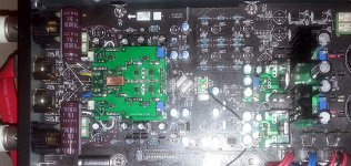
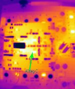
205 - active output module (stereo)
Finally, I could finish also the active stereo output modul for 205. Is based on OPA1632, and it sum two of the DAC output channels. DC coupled.
Now the ESS9038Pro it reveal indeed, its extraordinary dynamic...
Finally, I could finish also the active stereo output modul for 205. Is based on OPA1632, and it sum two of the DAC output channels. DC coupled.
Now the ESS9038Pro it reveal indeed, its extraordinary dynamic...
Attachments
Last edited:
OPPO Digital
OPPO Digital - It has been 14 years since we established... | Facebook
OPPO Digital - It has been 14 years since we established... | Facebook
What a pity, I do wish that's just a joke but it's really happening.We waited until it was no longer April Fool's Day to post this. This is not a prank or joke.
OPPO Digital
OPPO Digital - It has been 14 years since we established... | FacebookWhat a pity, I do wish that's just a joke but it's really happening.
Yep, wish it was no joke - besides, when did Oppo ever have a sense of humour?
Forbes: Oppo Announces Shock
Last edited:


- Home
- Source & Line
- Digital Source
- Oppo new UDP series players - 203/205 - Discussions, upgrades, modifications