Thanks, Coris.
Anything you would change ?
Thanks.
I would change it with mine...
")
Well, an observation about full copper heatsink. It is true that the copper it better conduct both heat and electricity (than aluminium). When about using copper as heatsink (quite powerful power supply), one should note that copper it absorb quicker the heat, but it hold it in it longer as well. The aluminium heatsink (in same conditions) it absorb slowly the heat, but it transmit it faster to the environment (it not have the tendance to keep it)...
The conclusion here is that aluminium it will be preferable as heatsink than copper (copper is more expensive as well).
Last edited:
Hi Coris,Just for your information. This is how it looks like on scope, the original headphone stage on 205 (no audio signal)...
Do you have those graphs for the oppo 203 standard psu vs your LPS?
Thanks
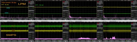
Here are some older graphs, comparing my LPS with original SMPS. The LPS it was improved since...
Please note that the LPS connected to the boards, it become more noisy. This is normal, and is caused by the very noisy digital stages, which it have impact over an "silent" LPS. However, the overall amount of noise in the system is much lower when the digital system is powered by a LPS.
To obtain a higher resolution for the graphs, it is better download it first.
Attachments

Just for your information. This is how it looks like on scope, the original headphone stage on 205 (no audio signal)...
What exactly are we looking at here? It's not good to present data to the public without context.
Where do I go to look at your products
I have already replayed to you. Please contact me on the provided e-mail.
What exactly are we looking at here? It's not good to present data to the public without context.
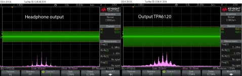
The graphs in the above post, are taken at the original headphone output of an 205, and at the TPA6120 outputs. TPA 6120 is used as the main chip for headphone stage on 105/205 (balanced to low impedance unbalanced converter).
As I mentioned before, and repeated in post 642, the headphone section of 205 it oscillate in Mhz range. These oscillations are not possible to impact the headphones connected to that output, and cannot be heard as well. In my opinion, it is not fortunate at all heving a such (enough large spectre) Mhz oscillator inside a audio/video device.
TPA6120 is well known as unstable if the PCB design is not carefully done. The design of the headphone section in 205, in conjunction with the attachement of a low impedance buffer after TPA6120, it make the whole circuit unstable, oscillating as pictured in my above post.
Oppo took some measures to minimise the level of the oscillations at the headphone connector, and this is to be seen in my graphs as well. The level of the oscillations is lower right on output.
However, the right measure here it should be remaking the PCB or circuit design so to not have these oscillations at all... Anyway, now the 205 it is not produced anymore, so nothing to be corrected by Oppo...
Last edited:
The graphs in the above post, are taken at the original headphone output of an 205, and at the TPA6120 outputs. TPA 6120 is used as the main chip for headphone stage on 105/205 (balanced to low impedance unbalanced converter).
As I mentioned before, and repeated in post 642, the headphone section of 205 it oscillate in Mhz range. These oscillations are not possible to impact the headphones connected to that output, and cannot be heard as well. In my opinion, it is not fortunate at all heving a such (enough large spectre) Mhz oscillator inside a audio/video device.
TPA6120 is well known as unstable if the PCB design is not carefully done. The design of the headphone section in 205, in conjunction with the attachement of a low impedance buffer after TPA6120, it make the whole circuit unstable, oscillating as pictured in my above post.
Oppo took some measures to minimise the level of the oscillations at the headphone connector, and this is to be seen in my graphs as well. The level of the oscillations is lower right on output.
However, the right measure here it should be remaking the PCB or circuit design so to not have these oscillations at all... Anyway, now the 205 it is not produced anymore, so nothing to be corrected by Oppo...
Thank you, Coris. So are these are open circuit oscillations or are they under some typical headphone load (32ohm - 600ohm)?
Thank you, Coris. So are these are open circuit oscillations or are they under some typical headphone load (32ohm - 600ohm)?
Well, I measured it without a headphone connected. The most frequent situation is the use of the player without a headphone connected. So, while one use the device for its line outputs, the Mhz range oscillations are present. I think this is the main problem.
However, I will measure again with a load connected (when I will get the next stock 205).
I use the same TPA6120 in my output module, and I am not heaving such oscillations, no matter with/without load... I appreciate TPA6120 as a very good device.
Last edited:
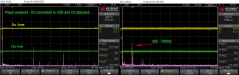
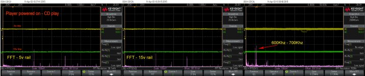
Replacing the original resonators on main board, with oscillators it have impact over both picture and sound. The impact it is subtle but obvious. It mean less noises on picture (even cleaner picture), and higher quality for digital sound out of the device. The LPS it reduce dramatically the overall noise in the system, while the oscillators (powered by battery) it contribute to lower even more the noise levels.
+/-12 regulators
Hi Mok
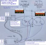
Based on you PM, I think you have the regulators reversed. +ve reg LM2940 is near center of unit and -ve reg LM7912 is near the edge.
Here is schematic of physical layout, showing TPS7A regulator pinouts as well.
Ignore the bottom part which refer to a "4 pole bd"
Denis
Last night I changed the two regulators on the audio board to the newclassD uwb II regulator and I lost the audio for all outputs..Coaxial, hdmi and RCA.
Wonder what I have done wrong that causes it.
Hi Mok
Based on you PM, I think you have the regulators reversed. +ve reg LM2940 is near center of unit and -ve reg LM7912 is near the edge.
Here is schematic of physical layout, showing TPS7A regulator pinouts as well.
Ignore the bottom part which refer to a "4 pole bd"
Denis
An externally hosted image should be here but it was not working when we last tested it.
Last night I changed the two regulators on the audio board to the newclassD uwb II regulator and I lost the audio for all outputs..Coaxial, hdmi and RCA.
Wonder what I have done wrong that causes it.
Ok, it mysteriously started working again.
Sorry all, this message was intended for a different forum. It was late...Ok, it mysteriously started working again.
I just discovered this forum last night, and read most of the articles in this thread. It seems that the objective for many of the mods is to reduce HF noise sources. My UDP-205 is unmodified, and I am wondering if the noise that I observe on the analog outputs is typical. See the attached scope pics.
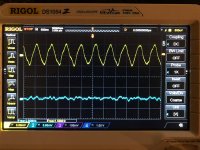
The first one shows the dedicated analog stereo outputs (RCA sockets, unbalanced), with USB DAC input selected, but no input signal. Left stereo channel (yellow) has 10mv p-p with fundamental frequency about 1.5MHz. Right channel is considerably quieter. The RCA sockets for FL and the other multi-channel outputs look similar to the right channel (blue) in this scope pic. Why is the dedicated left channel output so noisy, and others much cleaner?
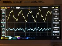
If I select Blu-ray as input, the noise on the dedicated stereo outputs is worse. Left channel has 20 mV p-p at 810kHz. See the second pic.
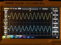
With USB DAC input selected, the headphone jack has 30mV p-p at 45MHz in both channels. See the third pic.
Is this normal for the UDP-205? I reported my results to Oppo's service center, with copies of the pics. They want me to send the unit in for repair. Perhaps there is something that they can fix (faulty shielding or decoupling caps, etc.). But if they find that the unit is working normally, within their specs, then sending it in is a waste of time.
Back in the 1980s, I did a lot of HiFi component modding and scratch building. Now I'm retired, and my ears are not as good as they used to be. So I am less motivated to spend time and money on hardware hacks in the Oppo. It does sound really good, in its current state. Just wondering if my unit is behaving unusually.
The first one shows the dedicated analog stereo outputs (RCA sockets, unbalanced), with USB DAC input selected, but no input signal. Left stereo channel (yellow) has 10mv p-p with fundamental frequency about 1.5MHz. Right channel is considerably quieter. The RCA sockets for FL and the other multi-channel outputs look similar to the right channel (blue) in this scope pic. Why is the dedicated left channel output so noisy, and others much cleaner?
If I select Blu-ray as input, the noise on the dedicated stereo outputs is worse. Left channel has 20 mV p-p at 810kHz. See the second pic.
With USB DAC input selected, the headphone jack has 30mV p-p at 45MHz in both channels. See the third pic.
Is this normal for the UDP-205? I reported my results to Oppo's service center, with copies of the pics. They want me to send the unit in for repair. Perhaps there is something that they can fix (faulty shielding or decoupling caps, etc.). But if they find that the unit is working normally, within their specs, then sending it in is a waste of time.
Back in the 1980s, I did a lot of HiFi component modding and scratch building. Now I'm retired, and my ears are not as good as they used to be. So I am less motivated to spend time and money on hardware hacks in the Oppo. It does sound really good, in its current state. Just wondering if my unit is behaving unusually.
Attachments
just a few observations...
1. Any reason why you are not loading the RCA outputs / headphone output when taking the readings?
2. If you feed a digital 0 to a digital source, the noise should drop dramatically.
205 is the most-universal-as-can be player around; HOWEVER, its sound is too clinical and unnatural for my taste; incapable of producing a natural timber / percussion / string instrumnets' sound - simply put, a way too overprocessed sound for my liking.
They are selling for around 4-5 even 6k at the moment, so if you are disappointed, the best thing to do would be to sell it (in its original, unmodified form) and make double / triple what you paid.
Thanks for the reply.
I did test the outputs with and without loads. The stereo RCA outputs are normally cabled directly to the inputs of an Aragon 4004 Mk II power amp. I looked at the headphone outputs with three different loads: 120 ohm resistors, connected to the power amp, and connected only to the scope. The loadings don't substantially change the HF garbage that I reported in the previous post.
There was a problem with the jack-to-RCA adaptor that I used for testing the headphone port. After fixing that, I measured an even larger oscillation in both headphone channels: 150mV p-p at 45 MHz, and amplitude modulated at about 600kHz.
I am not disappointed by this UDP-205. The sound quality is pretty damn fine, and I am listening through very revealing full-range electrostatic speakers (Acoustat 3). If I had to name a flaw, I might wish for a slight improvement in the depth of the stereo imaging. I don't know if a fix for the HF garbage would improve that, or any other aspect of SQ.
- Home
- Source & Line
- Digital Source
- Oppo new UDP series players - 203/205 - Discussions, upgrades, modifications