Measuring Clock Jitter
Hi JohnW,
If the clock output was fed into a monostable with say a pulse length set to 50% of the total of the clock pulse length for one complete clock cycle, then you would have a PWM output which is representative of the clock jitter. If this were filtered to remove the frequencies above say 40 to 100kHz, you could now use a sound card to measure the clock noise.
Regards
David
Measuring Clock Jitter
Hi All,
Here is a proposed jitter detector into which a clock can be fed directly and the jitter noise will apear on the output. This can then be viewed on a PC spectrum analyser.
I will spice the circuit and get back with the results.
Regards
David
Hi All,
Here is a proposed jitter detector into which a clock can be fed directly and the jitter noise will apear on the output. This can then be viewed on a PC spectrum analyser.
I will spice the circuit and get back with the results.
An externally hosted image should be here but it was not working when we last tested it.
Regards
David
Can anyone explain the differences between FM / PM in a langue I could understand – simple English would be a good start.
A PM modulation of a waveform is equal to the FM modulation of the waveform's derivative with respect to time.
Measuring Clock Jitter
Hi All,
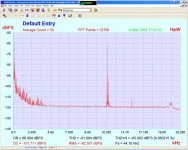
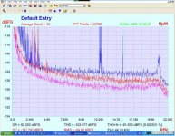
I have tried the circuit and although it does work the sensitivity is a bit poor for measuring clocks but does measure a signal generator FM modulated at around 11kHz as in the plot below. The modulation level is very small, probably less than 1nS as it is not visable on my scope. I know that the jitter on a TOSLINK connection is fairly obious when viewed directly on a scope screen so the circuit may be usefull for evaluating different TOSLINK cables or transmitter and receiver combinations/configurations.
Regards
David
Hi All,
I have tried the circuit and although it does work the sensitivity is a bit poor for measuring clocks but does measure a signal generator FM modulated at around 11kHz as in the plot below. The modulation level is very small, probably less than 1nS as it is not visable on my scope. I know that the jitter on a TOSLINK connection is fairly obious when viewed directly on a scope screen so the circuit may be usefull for evaluating different TOSLINK cables or transmitter and receiver combinations/configurations.
An externally hosted image should be here but it was not working when we last tested it.
Regards
David
Hi David,
With FM / PM all the information is contained in the frequency of the carrier and not in the amplitude modulation, the frequency of the carrier can be measured by observing the zero crossings of the carrier.
The clock input (which contains the FM / PM phase noise) triggers a monostable pulse generator, which produces a short pulse at each positive (or negative) edge transition of the clock. If you then integrate the output of the monostable, you will produce an output voltage proportional to the instantaneous input frequency.
It’s very difficult to observe LF (audio frequency) jitter on a Non-Storage Scope. With LF jitter, the cycle to cycle variation can be sub pS, its only when these cycle to cycle variations are integrated over a longer time (determined by the frequency BW of interest), can the full extent of the phase noise be determined, so your 11KHz modulation levels could be quite large – but still not be visible on the scope.
This is also the same reason that the sensitivity of your circuit is so low. To increase the sensitivity, the output of the monostable needs to be integrated, rather then simply filtered. As we are trying to observe LF phenomena, the integrator must accurately “store” this LF information and not allow the LF information content of the charge pulses “leak away”.
How to provide a correctly damped (i.e. produce no spurie) “DC” stabilisation loop for the integrator?
As the total area of the pulse output from the monostable (charge) will be integrated, any amplitude modulation of the PSU (noise) of this pulse will result in an error. Logic has no PSU rejection, so an ultra low noise PSU must be used for the Monostable / comparator.
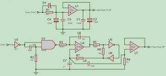
Using some of your original circuit values, the modified circuit could look something like this. U1 forms the Ultra low noise regulator to power the Logic Gates, U5, U6 form a simple High Speed comparator with a 2.5V slice point, C7, R7 form the DC stabilisation loop - they need to be calculated to provide the LPF corner fc point and achieve the correct Damping of the loop, to prevent “side-band spurie”. Ignoring the VLF voltage modulation required to stabilise the integrator's DC condition, the voltage modulation at the junction of R7 / C7 represents the LF phase noise of the clock (from DC to the LPF fc point). This is HPF by C8 / R4 to remove DC and VLF (integrator stabilisation correction voltage), and then buffered to provide the “audio” output to the FFT. U7 could also be configured to provide gain.
What do you think? is there a better method, also what FFT software do you use?
With FM / PM all the information is contained in the frequency of the carrier and not in the amplitude modulation, the frequency of the carrier can be measured by observing the zero crossings of the carrier.
The clock input (which contains the FM / PM phase noise) triggers a monostable pulse generator, which produces a short pulse at each positive (or negative) edge transition of the clock. If you then integrate the output of the monostable, you will produce an output voltage proportional to the instantaneous input frequency.
It’s very difficult to observe LF (audio frequency) jitter on a Non-Storage Scope. With LF jitter, the cycle to cycle variation can be sub pS, its only when these cycle to cycle variations are integrated over a longer time (determined by the frequency BW of interest), can the full extent of the phase noise be determined, so your 11KHz modulation levels could be quite large – but still not be visible on the scope.
This is also the same reason that the sensitivity of your circuit is so low. To increase the sensitivity, the output of the monostable needs to be integrated, rather then simply filtered. As we are trying to observe LF phenomena, the integrator must accurately “store” this LF information and not allow the LF information content of the charge pulses “leak away”.
How to provide a correctly damped (i.e. produce no spurie) “DC” stabilisation loop for the integrator?
As the total area of the pulse output from the monostable (charge) will be integrated, any amplitude modulation of the PSU (noise) of this pulse will result in an error. Logic has no PSU rejection, so an ultra low noise PSU must be used for the Monostable / comparator.
Using some of your original circuit values, the modified circuit could look something like this. U1 forms the Ultra low noise regulator to power the Logic Gates, U5, U6 form a simple High Speed comparator with a 2.5V slice point, C7, R7 form the DC stabilisation loop - they need to be calculated to provide the LPF corner fc point and achieve the correct Damping of the loop, to prevent “side-band spurie”. Ignoring the VLF voltage modulation required to stabilise the integrator's DC condition, the voltage modulation at the junction of R7 / C7 represents the LF phase noise of the clock (from DC to the LPF fc point). This is HPF by C8 / R4 to remove DC and VLF (integrator stabilisation correction voltage), and then buffered to provide the “audio” output to the FFT. U7 could also be configured to provide gain.
What do you think? is there a better method, also what FFT software do you use?
Attachments
Measuring Clock Jitter
Hi JohnW,
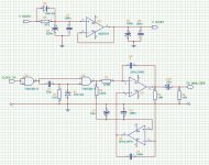
Great! I like the circuit but I think another integrator used to DC stabilise the signal integrator may be a better solution as the signal integrator output is then being directly monitored by the analyser and also there is very little noise injected into the circuit by the DC stabilising integrator as it is not a switching element. I noticed that your stabilising element is non inverting, has hysteresis has the integrated clock noise passing through it before it is passed on to the buffer amp. I could not see that this would give an accurate output voltage at the buffer proportional to the integral of the monostable output.
Your thoughts would be of interest.
I would like to try the new circuit as soon as possible to see what results are obtained.
HpW Works is the analyser which I mainly use plus other analysers such as SpectraLab and one from Dr Jordon (sometimes available on USA ebay for around $20 to $25).
Regards
David
Hi JohnW,
Great! I like the circuit but I think another integrator used to DC stabilise the signal integrator may be a better solution as the signal integrator output is then being directly monitored by the analyser and also there is very little noise injected into the circuit by the DC stabilising integrator as it is not a switching element. I noticed that your stabilising element is non inverting, has hysteresis has the integrated clock noise passing through it before it is passed on to the buffer amp. I could not see that this would give an accurate output voltage at the buffer proportional to the integral of the monostable output.
Your thoughts would be of interest.
I would like to try the new circuit as soon as possible to see what results are obtained.
HpW Works is the analyser which I mainly use plus other analysers such as SpectraLab and one from Dr Jordon (sometimes available on USA ebay for around $20 to $25).
Regards
David
Attachments
Measuring Clock Jitter
Hi JohnW,
If you fed your circuit with a clock modulated with white noise and the circuit was demodulating correctly then you would have a flat line on a spectrum analyser. As the output is integrated, would you not have a sloping line with a large output at the low frequencies and a small output at the high frequencies as the integrator gain changes with frequency?
As the sensitivity is low - should it not just be a multiplier (amp with gain) on the output to raise the sensitivity of the circuit as long as the noise introduced by the amplifier is negligibly small?
Regards
David
Hi David,
Sorry for my last post, it appears I need to learn to spell….
The hysteresis should not be a problem; this just introduces a small DC error. Its true that U5, U6 could add noise, but would there noise contribution be any worst then the unfiltered noise of U5 in your circuit? – I really cannot comment…
Even though you take you output directly from the integrators O/P, it will still contain any noise introduced by the DC servo (OPAMP, resistor noise etc). The difference in my configuration is that it’s taken after LPF, again as to which is better, I would really not like to say, but one things for sure, if we keep throwing the suggestions and ideas back and forth – we will crack this nut eventually!
The DC accuracy of the circuit is not so import, just as long as it’s stable. The DC is removed by the output-coupling cap anyway. In the past, when I’ve tried my the configuration I’ve always found LF “Spurs” offset about the carrier on the output of the integrator. Maybe these could be removed by correct RC component values (damping) - but I’m not sure.
I’ve never used a second integrator for DC servo correction for the main integrator, so it would be interesting to see your results. My concern is that there’s no filtering on the output of the DC servo, so any servo noise is directly pumped into the main integrator – while to a limited degree, this is also true in my scheme, my method has the advantage that any noise is filtered by the LPF.
The main integrator must have very low input bias current, to preserve the LF charge information.
Hi David,
As I can’t simulate the circuit (my simulator - Labcenter’s Proteus is really poor with mixed signal Sims), It seems likely you will have gain drop at HF, but how much gain droop within the audio band with a 11MHz (256fs) or 16MHz (384fs) integrator output I could not say. At the end of the day, any gain drop could be compensated by a calibration plot anyway.
The problem with trying to directly amplify the output comes down to noise, the noise floor is already –130dB, the noise floor of a 5534 is about –150dBc @ 1Hz BW, so the only real way to improve the circuits performance is to directly improve its sensitivity with the integrator.
How good is your simulator? at this time I’m open to any suggestions.
Regards, John
Measuring Clock Jitter
Hi JohnW,
I have added a X22 amplifier on the output (NE5534) which does add its own noise because of the gain as can bee seen by the noise floor rising to -125dB, but the jitter signal can now be seen much more easily.
I am not sure how much noise the intergrator would add but as it has a gain of around -1.08 at 20Hz, it should be quite small.
I have added a plot of the circuit with a X22 amp on the output - a quieter amp such as a AD797 would give improved noise floor results.
I am still not sure why you suggest integrating the output - could you explain further?
Regards
David
Attachments
Measuring Clock Jitter
Hi JohnW,
I have fed a couple of clocks into the monostable with the x22 amp and have got some plots which do actually measure some difference between the two clocks, so with a bit of development it may still give better results.
My sim is a little temperamental also.
Regards
David
Hi JohnW,
I have fed a couple of clocks into the monostable with the x22 amp and have got some plots which do actually measure some difference between the two clocks, so with a bit of development it may still give better results.
My sim is a little temperamental also.
Regards
David
Attachments
Measuring Clock Jitter
Hi All,
There is of course the mixer approach as has been pointed out by HpW of HP Works but it does require two clocks and to remove any beat tones and a PLL is also needed. This may prove interesting reading or stimulation for a design.
http://www.wenzel.com/documents/measuringphasenoise.htm
and
http://www.wenzel.com/pdffiles/lowamp.pdf
Regards
David
Guys,
I just wanted to discuss some jitter aspects, including jitter mesurements. This thread is really a pleasure to read, for me.
I just wanted to open up a little more the jitter measurement discussion, in a direction already tauched by some one of the members.
I have ben working a little by myself in the last months, and came up with a tentative preliminary version of an article for TNT. The article is part of a series about digital inteconnections, and the specific topic is a discussion of the standard SPDIF connection, in my case through an electrical interconnect, with reclocking just before getting ot of the transport. But after some measures, the major discussion has moved to what happens at the receiver side.
The results are in some extent rather extreme, in my view, and I do not feel so comfortable with them, to the extent that I am setting up a system similar to David's one just to confirm all these data.
I just add a link to this pre-release version of the article, it is hosted on a blind link of the TNT server, just to make it available to all of you that might be interested to discuss results.
The other measurement system I have been setting up should help me in confirming these results in the next few days. I should be now ready to start serious measures.
If you also can help me in discussing the results and checking if what I think I have seen is real, I would really appreciate.
By the way, I have found out recently an article on TNT of someone else that used something very similar to my setup.
What I really find strange, is that the results seem so immediate and easily available, but I have never heard anyone discussing anything similar. So there might really be something wrong in the approach (yes, but whose approach???).
The link is www.tnt-audio.com/clinica/spdif_reclocking_e.html
Thank you all in advance for your patience
(I am afraid you'll need plenty... trust me, if you cannot understand is only because you have not seen the size of the article...)
Giorgio
What an interesting thread.
I'll ask some neophyte questions:
- Do I understand correctly that the often used Miller Audio Research gear (and the way it is often interpreted for its results) does not cut it at near 100ps anymore?
- It is possible to build a rather inexpensive jitter measurement device that is quite accurate by using a sound card + software analyzer + simple schematic device as listed in this thread?
- Is the accuracy of such measurements limited by the accuracy of the clock on the sound card?
- Is it possible/worthwhile to replace the clock of a say, RME DIGI 96/8 sound card (used on HpWorks page as an example) with a low jitter clock such as TentLabs Xo2? This would have to be on a separate board, in a separate PCI slot, using +5V/+12V feeds from a normal/noisy computer PSU.
Somewhat off-topic...
I will also offer the following document links to those who may not yet know about them (probably not very useful to the discussers in this thread, but perhaps other lurkers like me):
Jitter Theory - Part 1 'Interface Jitter' (Julian Dunn, Audio Presicion, Newsletter vol 14, no. 1)
http://www.aesitalia.org/Materiale/archivio_documenti/AP - Jitter Theory (1).pdf
Jitter Theory - Part 2 (Julian Dunn, Audio Presicion, Newsletter vol 15, no. 1)
http://www.aesitalia.org/Materiale/archivio_documenti/AP - Jitter Theory (2).pdf
TOWARDS COMMON SPECIFICATIONS FOR DIGITAL AUDIO INTERFACE
JITTER (Julian Dunn, et. al., Nanophon)
http://www.nanophon.com/audio/towards.pdf
Jitter: Specification and assessment in digital audio equipment (Julian Dunn, Nanophon)
http://www.nanophon.com/audio/jitter92.pdf
Diagnosis and Solution of jitter-related problems in digital audio (Julian Dunn, Ian Dennis, Prism Sound)
http://www.nanophon.com/audio/diagnose.pdf
On Jitter (Dan Lavry, dB Technologies)
http://www.lavryengineering.com/white_papers/jitter.pdf
Converting between RMS and Peak-to-Peak Jitter at a
Specified BER (Maxim Integrated Products)
http://pdfserv.maxim-ic.com/arpdf/AppNotes/3hfan402.pdf
Jitter and Its Effects (Benchmark Media Systems)
http://cmd.bweb..http://www.benchmarkmedia.com/appnotes-d/jittercu.asp
Why Jitter is Important (Audio Precision, offline, but copy without images available from the Internet Archive)
http://web.archive.org/web/19971224043235/http://audioprecision.com/publications/jan96.htm
Some jitter measurements of transports and cd-rs
http://members.chello.nl/~m.heijligers/DAChtml/jittermeas/jitter.html
Verifying Jitter Measurement Accuracy
http://www.techonline.com/community/tech_group/29107
Jitter - Understanding, measuring, eliminating (Johnnie Hancock, Agilent)
http://www.highfrequencyelectronics.com/Archives/Apr04/HFE0404_Hancock.pdf
Measuring Clock Jitter Spectra (Paul Winser, London DIY Hifi Circle)
http://www.earthcurrents.com/london-live/cd-jitter.pdf
http://www.earthcurrents.com/london-live/measuring-jitter-spectra.pdf
Why Jitter matters in high resolution digital audio systems (Peter Schut, Axon)
http://www.broadcastpapers.com/audio/Jitter1-rev1.PDF
Theoretical and Audible Effects of Jitter on Digital Audio Quality _ Eric Benjamin and Benjamin Gannon, Dolby Laboratories, Inc., San Francisco, CA, USA
http://www.aes.org/publications/preprints/lists/105.html
Some of the stuff is quite old and some implementations may be considered outdated, but for leaning they are helpful (imho).
I cannot vouch for the accuracy of the above papers, but they've been helpful to me in understanding jitter, measurements, effects and audibility.
cheers,
halcyon
Since I missed this one first time around.......
I would imagine that the jitter of a TOSLINK would be around 1 nSec or so. A really lousy setup. The rise and fall times are slow, and asymetrical. So, I would expect it to sound like crap.
And it does.
As for fiber....this applies to laser and glass transmission........
Fiber was designed to start working at distances where copper craps out........IOW at 1 km or so. It will work at shorter distances, but suffers from pulse distortion due to mode hopping in the laser. Which translates into jitter.
It also sounds like crap.
Unless done right. Which no high-end company ever figured out. Eventually, even Stereofile had to publish results that showed glass fiber setups had lots of jitter. (Some of us tried to tell them......but we didn't count.)
But don't take my word for it......ask Lucent (or whatever the old ATT Labs company is called), who made the laser parts that Wadia and Krell used. They will tell you: designed for links greater than 1 km.
Jocko
Re: Since I missed this one first time around.......
Actually fiber optics in computer networks go much further than 1km, but that's a completely different story.
Not the crap transmitters, receivers and cheap plastic used in (audio) optical cables.
Actually, you shouldn't pass around 15 meters.

Jocko Homo said:Fiber was designed to start working at distances where copper craps out........IOW at 1 km or so. It will work at shorter distances, but suffers from pulse distortion due to mode hopping in the laser. Which translates into jitter.
Actually fiber optics in computer networks go much further than 1km, but that's a completely different story.
Not the crap transmitters, receivers and cheap plastic used in (audio) optical cables.
Actually, you shouldn't pass around 15 meters.
Hi,
I have some questions to experts of digital audio here.
To me the jitter introduction by optical transmission lines is quite new; I was always thinking that it is caused by D/A converters only.
I am a computer tech guy and view TOSlink cable as a data cable to transfer digital information. So, in order to play it, the digital receiver must recover data bit-to-bit, and map incoming signal to it's own clock for D/A conversion? Perhaps some recovery algorithms are used to correct for dropped bits like its common in computers?
So how can this affect sound quality at all? Do I misunderstand how it works?
Regards,
Lukas.
The bits are not the problem. Timing is the problem. Most DACs derive their output data timing from a PLL locked to the incoming data timing. The PLL filters out high frequency jitter, but can't (in fact, mustn't) fiddle with low frequency jitter. It appears that basic optical transmission systems introduce more jitter than basic coaxial cable systems. Hence for short distance cable is better. For long distances optical is better, but if you want to preserve timing then you need something better than the basic setup.
There is ususally a sample-and-hold function in the D/A process. Each sample is held constant until the next conversion. This results in a stepped signal, which in turn will be filtered to remove unwanted components. Now, even if the individual samples are 100% accurate in their amplitude, the inaccuracy in the conversion timing (that is jitter) results in deviation from the original energy of each sample. I use the loosy word "energy" to describe the area of the sample (integral of amplitude over a sample period). The net result is that the signal does not match the original analog waveform after filtering. It can be perceived as noise and/or distortion.
- Status
- This old topic is closed. If you want to reopen this topic, contact a moderator using the "Report Post" button.
- Home
- Source & Line
- Digital Source
- How much jitter...