Hi,
I just finnished building the cct below and am listening as I type
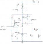
This version is designed for 12.7V battery operation.
At first is was not stable so I added the 1nF caps, I am not using a ground plane which might explain the need for them. -3dB about 100Khz
I have 10uF film caps on the board at present - I will try other values later.
The "Three diodes" are in fact red LEDs. I will try putting 1uf caps across these later. In simulation it seems to have a noticable effect.
This cct sounds really very good very detailed but also smooth a refined. The words natural and organic come to mind...")
Many thanks to Rudolf and any others involved in the development of this cct
I just finnished building the cct below and am listening as I type
This version is designed for 12.7V battery operation.
At first is was not stable so I added the 1nF caps, I am not using a ground plane which might explain the need for them. -3dB about 100Khz
I have 10uF film caps on the board at present - I will try other values later.
The "Three diodes" are in fact red LEDs. I will try putting 1uf caps across these later. In simulation it seems to have a noticable effect.
This cct sounds really very good very detailed but also smooth a refined. The words natural and organic come to mind...
Many thanks to Rudolf and any others involved in the development of this cct
Attachments
One thing that I did not mention is that in implementing this I took the oportunity to have a fairly ideal earthing scheme.
The only point where the two channels have a common earth is just by the DAC. All the other supplies and earths are separated for each channel
In theory this should help.....
mike
The only point where the two channels have a common earth is just by the DAC. All the other supplies and earths are separated for each channel
In theory this should help.....
mike
sparkle said:... And the transistors?
daniel
Well I used some faily high gain ( 400 - 500 ) that I had to hand.
If I where to buy new I would go for BC550C & BC560C or similar
mike
mikelm said:Hi,
I just finnished building the cct below and am listening as I type
This version is designed for 12.7V battery operation.
At first is was not stable so I added the 1nF caps, I am not using a ground plane which might explain the need for them. -3dB about 100Khz
I have 10uF film caps on the board at present - I will try other values later.
The "Three diodes" are in fact red LEDs. I will try putting 1uf caps across these later. In simulation it seems to have a noticable effect.
This cct sounds really very good very detailed but also smooth a refined. The words natural and organic come to mind...
Many thanks to Rudolf and any others involved in the development of this cct
Hello Mike,
while looking for a suitable output stage for my new experimental TDA1545 dac I stumbled on your project, that would allow me to use battery power... but I need a few clarifications:
the vref input is the vref pin of the dac? I guess that such pin, on the DAC side, should be used as usual (or not?)
The V/I resistor is the 999 Ohm just before the output cap, if its value calculated for the 1543?
Regards
Andrea
Andypairo said:
the vref input is the vref pin of the dac? I guess that such pin, on the DAC side, should be used as usual (or not?)
The V/I resistor is the 999 Ohm just before the output cap, if its value calculated for the 1543?
Hi Andrea,
The Vref is fed into this cct and as you can see goes through two diode junctions one npn and one pnp - which means that, more or less, the same voltage is presented at the i/p from the DAC
I designed this cct for the 1545 and from memory I think that the same Vref is fed into the DAC aswell ( I can't find the manual at the moment ) The function of this is to allow the DAC drive into the voltage that it is most comfortable with. I think it will also work with the 1543
For best quality it is very important that the Vref is very clean so I would at least regulate this supply from the analogue battery or better still give it it's own battery. The Vref itself is can gained with two resistors with a cap across the o/p if the supply is clean. I think it has to be 2/3 of the supply voltage to the 1545.
If you have not tried alkaline non rechargable batteries yet you may be in for a pleasant suprise - only trouble is we then got to work out a way of replicating their sublime sound that avoids having to buy new batteries all the time.
The 1000 ohm resistor at the o/p is what finally converts the current to voltage and as such the value could be altered to suit your requirements. I used a non-inductive wire wound from RS for this resistor and the quality is excellent.
I would be very interested to hear how you get on with this
good luck
mike
- Status
- This old topic is closed. If you want to reopen this topic, contact a moderator using the "Report Post" button.
- Home
- Source & Line
- Digital Source
- "super pair" I/V new 12.7V version