Hi, take that all and you have a short between test points.
Right on the deadly slip of the probe the CD spinned like crazy counter clockwise and never spinned again. The lense goes up and down, but then no spin at all. Try to focus, try but...
And yes, you can throw me stones, that is on a Sony KSS151A in a TEAC player. =(
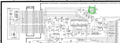
Check on attachement, that was the 22R used to check current used at laser diode, so the 22R was shorted and become 0R for a while.
Did I kill my laser or did another part (Q401?) sacrifice itslef for the sake of my wallet?
Any experienced CD killer to help me sort it out?
Man I've forgotten this happens in our hobby...
F@*#!
Right on the deadly slip of the probe the CD spinned like crazy counter clockwise and never spinned again. The lense goes up and down, but then no spin at all. Try to focus, try but...
And yes, you can throw me stones, that is on a Sony KSS151A in a TEAC player. =(
Check on attachement, that was the 22R used to check current used at laser diode, so the 22R was shorted and become 0R for a while.
Did I kill my laser or did another part (Q401?) sacrifice itslef for the sake of my wallet?
Any experienced CD killer to help me sort it out?
Man I've forgotten this happens in our hobby...
F@*#!
Attachments
Hi Malefoda,
I'm afraid that you would have sent that poor laser diode extremely high current. It's dead, dead as a door nail. If you look at the schematic you provided, look at what that resistor does. It is the only thing that limits the current from Q401.
Before trying a new head, make absolutely certain that Q401 is okay, because if it shorted, you will blow the following laser diodes as fast as you can plug them in. I am not kidding you. I'm very sorry for the bad news.
-Chris
Sorry to hear that, i know how it feel too when a well loved cd player is dying or not functioning properly after some tweaks/changes.
If it's really a precious CD player to you, why not give a try to ressurect it and learn a bit more how it work at the same time ?
Sure, i'm not talking about going as far as using professionnal equipments for measures and calibration and doings some astonishing maths but just some dumb "plug'n play".")
If i were you, i would try to replace the dead laser with one of these after checking that components next to it are alright :
Sony KSS 151A 3mW 5mW 780nm 5 6mm TO18 Infrared IR Laser Lazer Diode LD | eBay
In this video at 11:05 minutes you can see where the laser diode emplacement is (this is maybe not the exact same assembly but it should be very similar) :
https://www.youtube.com/watch?v=oWVhB1BEGBg
If it works : Bingo, else : well, you tried your best and won't have much regrets anyway.
If it look too difficult for you you could ask to a an electronics specialized reparator (by giving him the laser and the assembly) or someone who is really in this kind of stuff to mount it for you ?
You can also wait or search for a complete assembly (scapped from an another player) alongside as you said.
If it's really a precious CD player to you, why not give a try to ressurect it and learn a bit more how it work at the same time ?
Sure, i'm not talking about going as far as using professionnal equipments for measures and calibration and doings some astonishing maths but just some dumb "plug'n play".
If i were you, i would try to replace the dead laser with one of these after checking that components next to it are alright :
Sony KSS 151A 3mW 5mW 780nm 5 6mm TO18 Infrared IR Laser Lazer Diode LD | eBay
In this video at 11:05 minutes you can see where the laser diode emplacement is (this is maybe not the exact same assembly but it should be very similar) :
https://www.youtube.com/watch?v=oWVhB1BEGBg
If it works : Bingo, else : well, you tried your best and won't have much regrets anyway.
If it look too difficult for you you could ask to a an electronics specialized reparator (by giving him the laser and the assembly) or someone who is really in this kind of stuff to mount it for you ?
You can also wait or search for a complete assembly (scapped from an another player) alongside as you said.
Hi,
that sounds nice in fact! I was not aware of the laser diode change only. It is worth the try and yes I may learn form it. I have basic gear to check when it's done, DDM and scope. A nice long cold winter hobby, I'll keep this thread updated in case I am not the only laser murderer around
Thanks!
that sounds nice in fact! I was not aware of the laser diode change only. It is worth the try and yes I may learn form it. I have basic gear to check when it's done, DDM and scope. A nice long cold winter hobby, I'll keep this thread updated in case I am not the only laser murderer around
Thanks!
Last edited:
I don't think shorting that resistor is likely to have killed the laser diode. It's not the current limiter for the LD, only a bit of voltage drop for Q401. There is some definite chance of killing Q401, which would maybe have a shot at damaging U401, either of which are more likely than LD damage. First thing is to meter-check Q401, and then see if you are getting an LD-on signal from U401. Even if Q401 didn't cook, the surge from resistor short could have damaged the chip.
Hi Stephen,
Nope, dead wrong.
How do you make a constant current source using a transistor, three resistors and an LED (could be any voltage source, like that IC for example). What happens to the current if you reduce the resistance from emitter to it`s zero reference (+5V). Now short it and tell me how high the current gets. In this case, the current monitor diode will react to the high light output, but there is a 47 uF capacitor hanging between base and +5 V that will maintain that voltage for a short while. Problem is, the emitter goes from its normal resting voltage (Approx. 1.1 VDC assuming Iop=50 mA) pretty much instantly, so there is a period of time where the E-B voltage will be dropping from about 1.8 VDC back down to the Vbe that previously existed. Without a detected laser current now (`cause it burned out), the current will rise to some limiting value where the circuit can`t conduct any more than it is. The result, an ex-laser diode. I`ve watched technicians do this same thing over the years, and the result doesn`t often change. Laser diodes don`t like even the most brief pulse of high current.
The current monitor diode can`t anticipate what is going to happen, it can only signal a high light output once it is happening. Everything happens quickly except for that darned base voltage due to the 47uF 10 VDC capacitor. That is the thing that causes this circuit to be a diode killer with a short across R407, 22R. If it survived, and I don`t think it did, I wouldn`t trust it.
Best, Chris
Chris is right, the laser diode will be dead or damaged such that its output will be a fraction of normal.
It only takes a split second to kill an LD.
There is only one proper way to adjust laser output and it is with one of these:

If you cannot achieve the rated emission within the current range specified, then the laser is no good. No amount of 'turning it up' will help. I just wish people would leave LD adjustment pots alone, 9 out of 10 times the problem doesn't lie with the laser and they wreck a good laser head for no good reason.
It's akin to putting banana peels in a squealing differential by dodgy used car dealers back in the day, making it work just long enough to sell it to some unsuspecting buyer.
It only takes a split second to kill an LD.
There is only one proper way to adjust laser output and it is with one of these:
If you cannot achieve the rated emission within the current range specified, then the laser is no good. No amount of 'turning it up' will help. I just wish people would leave LD adjustment pots alone, 9 out of 10 times the problem doesn't lie with the laser and they wreck a good laser head for no good reason.
It's akin to putting banana peels in a squealing differential by dodgy used car dealers back in the day, making it work just long enough to sell it to some unsuspecting buyer.
Attachments
Last edited:
I reckon transistor's good, laser diode's dead. Transistor conducted more current (through a diode of course , which probably took a diode out. Transistor should be okay unless LD has shorted. Just replace the transistor with similar or equivalent type, and see if it works again.
U401, pin 2 will give you RF out readout peak-peak value... I think... difficult to read...
Good luck,
Nick
, which probably took a diode out. Transistor should be okay unless LD has shorted. Just replace the transistor with similar or equivalent type, and see if it works again. U401, pin 2 will give you RF out readout peak-peak value... I think... difficult to read...
Good luck,
Nick
Tried things before the long waiting for the LD to get here.
Tested the transistor Q401, tester said PNP OK, had a look in my spares (for my main untouched VRDS) and found not only my saved KSS151A never tested but "used but good" (hope so...) but aslo another one from I don't remeber where. I've fitted this last one in and the player spins and makes noises and never reads anything, but the TOC once. At the RF test point it's here, I just don't know if the amplitude is ok or if it can work (laser state unkown), and the adjustement procedure states things with a playing CD...
Beside I've removed the murdered LD from the laser assy, that damn thing is tiny! I've also messed with several tiny screws here, so mis-aligned the focus upper system, even if leveling system with spring and screws is far from perfect even factory-set. If it works with a new laser that will be a miracle! (In fact one only need to desolder the diode and then pull it out).
Last edited:
There's no call to be rude. And you might respect that I have >35 years pro service experience in this field.
What has a CCS got to do with this circuit? The xstor is a chip-controlled voltage regulator, not a CCS of any sort. Shorting the resistor only changes reference point of the reg, causing a momentary elevation of the voltage delivered to the LD. Whether enough to damage the LD, maybe, but it's not the same as turning a CCS full "on".
What has a CCS got to do with this circuit? The xstor is a chip-controlled voltage regulator, not a CCS of any sort. Shorting the resistor only changes reference point of the reg, causing a momentary elevation of the voltage delivered to the LD. Whether enough to damage the LD, maybe, but it's not the same as turning a CCS full "on".
Hi Stephen,
Nope, dead wrong.
How do you make a constant current source using a transistor, three resistors and an LED (could be any voltage source, like that IC for example). What happens to the current if you reduce the resistance from emitter to it`s zero reference (+5V). Now short it and tell me how high the current gets. In this case, the current monitor diode will react to the high light output, but there is a 47 uF capacitor hanging between base and +5 V that will maintain that voltage for a short while. Problem is, the emitter goes from its normal resting voltage (Approx. 1.1 VDC assuming Iop=50 mA) pretty much instantly, so there is a period of time where the E-B voltage will be dropping from about 1.8 VDC back down to the Vbe that previously existed. Without a detected laser current now (`cause it burned out), the current will rise to some limiting value where the circuit can`t conduct any more than it is. The result, an ex-laser diode. I`ve watched technicians do this same thing over the years, and the result doesn`t often change. Laser diodes don`t like even the most brief pulse of high current.
The current monitor diode can`t anticipate what is going to happen, it can only signal a high light output once it is happening. Everything happens quickly except for that darned base voltage due to the 47uF 10 VDC capacitor. That is the thing that causes this circuit to be a diode killer with a short across R407, 22R. If it survived, and I don`t think it did, I wouldn`t trust it.
Best, Chris
Gentleman, please
Firstly, solid state laser diodes are easily damaged by excess current. If that is in the form of a spike then I always understand that the timescale was in the very low hundreds down to tens of pico seconds time range for the facets to sustain damage. That damage may or may not be obvious and may show up many hours later during operation.
The 22 ohm adds a huge amount of 'compliance' for want of a better word. Strictly speaking the circuit should function in a steady state condition without it but you would find that slight changes in chip drive voltage cause very large changes in the LD current. The 22 ohm means that the chip drive voltage can range from say 2 to 4 volts giving an LD current of say 20 to 70ma rather than a change of just a hundred mv doing the same without the 22 ohm fitted. The laser is operated in a constant current condition at all times, the complication is that the current is ill defined across LD devices and ambient temperature. So its constant at any given moment, but subject to long term change as the device ages or temperature alters.
The big problem is what happens during the sudden step change in operating conditions such as will occur when shorting out that resistor, and I think this is what Chris is getting at. In the milliseconds (or microseconds) after the short appears, C403, the 47uf dumps its excess charge in the form of a current pulse into the B-E junction thus fully saturating the transistor for an instant. The LD is effectively connected across the 5 volt rail momentarily and that is when the damage occurs.
The 22 ohm also performs another critical function... its a fail safe in the event that the LD goes short and the transistor tries to dump the 5 volt rail to ground. The tiny inductor also plays a role in removing any HF noise present in the drive current to the LD. Any brief overvoltage (noise or otherwise) would 'spike' the LD and possibly cause impairment. Yes, they are that critical and sensitive to overcurrent.
Hi Stephen,
I'm not being rude, but it's clear you don't understand how that circuit works. Your years of toil in this field aren't known by everyone, including me - not that it matters. What matters is how this circuit works.
I compared this circuit to a CCS because the basic operation is the same if you neglect the dynamic nature of how the system works. This simplified view of the circuit should have given you something more familiar so you could recognize the basic nature of the circuit. From that point of view, I was hoping you would understand how it worked, and what shorting R407 would do.
C403 helps maintain the emitter-base voltage of Q401. The current through Q401 and the resistor R407 sets the voltage equal to (current * R407) + Vbe. If you suddenly short R407, the Vbe of Q401 becomes so high that Q401 saturates completely until C403 is discharged, the current through Q401 and the laser diode is only limited by the bulk resistance of Q401 and the laser diode. This then increases as soon as the laser diode shorts to even higher levels that Q401 may, or may not be able to survive. I have seen them short as well. So the peak current through the laser diode and Q401 is momentarily only limited by the external power supply and the bulk resistances of Q401 and the laser diode. This is assuming that U401 can react quickly enough to avoid a current spike, which it doesn't because if nothing else, C403 supplies the base current long enough to cause that destructive event.
Since the light output from the laser head spikes, then falls to zero (laser diode shorted or open), the fact that it is controlled by a feedback loop that has been broken means current rises to the full amount that the power supply and circuit resistances can provide. Only if the short across R407 is removed can those levels drop to a value determined mostly by the power supply and R407. It will remain in this state as long as power is supplied to that circuit.
I have had CD players come in, in that condition. Maybe not due to a short, usually because someone turns the laser up too high and the laser diode fails short. The end result is a shorted laser diode and cooked R407 and Q401. Sometimes Q401 follows the laser into the great beyond.
These circuits are not voltage controlled because as the laser diode heats up, the voltage across its terminals will drop lower. The rate of change of laser current per volt is very high compared to the parameter we want to control, the laser current. Therefore it is the laser current and light output that is controlled and sensed. The voltage drop across the laser diode is a byproduct of current flow and unreliable as a method for controlling power output. The output of all those light sensitive diodes (A,B,C,D,E and F, plus the monitor diode) is a current, not a voltage.
There it is all laid out. This circuit is a current controlled system. Voltage never enters into it beyond what you can incidentally read across the various elements, which change with temperature although the current remains close to constant. The only place we read a voltage is across R22, allowing us to infer the current flow from. That's easier than breaking the loop in order to use a current meter.
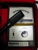
I also use the Leader LPM-8000 laser power meter for those systems where you set output power rather than operating current. Its also an easy way to determine what the state of the laser diode (coupled with the calculated current draw through R407). Most laser heads have a marking on them somewhere that indicates what the normal current to expect is. You are allowed 10% over before condemning the head as bad.
Best, Chris
I'm not being rude, but it's clear you don't understand how that circuit works. Your years of toil in this field aren't known by everyone, including me - not that it matters. What matters is how this circuit works.
Nope. That circuit is much closer to a CCS than a voltage regulator. It regulates current, not voltage. Its purpose is to run the laser diode at some current level to maintain a steady light output. The error sensor is the light sensitive monitor diode which feeds back into the IC. The error amplifier dynamically adjusts the drive on Q401 to maintain the light output of the laser diode at a somewhat constant level. The reflectivity of the disc can affect the light sensed by the monitor diode with some heads as well. That will modify the output power (reduces slightly) of the laser diode. As the laser diode and Q401 warm up, a change is also needed to maintain a semi-constant light output. If it weren't for the changes that occur in efficiency due to heat, a CCS could be used to control the power output.What has a CCS got to do with this circuit? The xstor is a chip-controlled voltage regulator, not a CCS of any sort.
I compared this circuit to a CCS because the basic operation is the same if you neglect the dynamic nature of how the system works. This simplified view of the circuit should have given you something more familiar so you could recognize the basic nature of the circuit. From that point of view, I was hoping you would understand how it worked, and what shorting R407 would do.
C403 helps maintain the emitter-base voltage of Q401. The current through Q401 and the resistor R407 sets the voltage equal to (current * R407) + Vbe. If you suddenly short R407, the Vbe of Q401 becomes so high that Q401 saturates completely until C403 is discharged, the current through Q401 and the laser diode is only limited by the bulk resistance of Q401 and the laser diode. This then increases as soon as the laser diode shorts to even higher levels that Q401 may, or may not be able to survive. I have seen them short as well. So the peak current through the laser diode and Q401 is momentarily only limited by the external power supply and the bulk resistances of Q401 and the laser diode. This is assuming that U401 can react quickly enough to avoid a current spike, which it doesn't because if nothing else, C403 supplies the base current long enough to cause that destructive event.
Since the light output from the laser head spikes, then falls to zero (laser diode shorted or open), the fact that it is controlled by a feedback loop that has been broken means current rises to the full amount that the power supply and circuit resistances can provide. Only if the short across R407 is removed can those levels drop to a value determined mostly by the power supply and R407. It will remain in this state as long as power is supplied to that circuit.
I have had CD players come in, in that condition. Maybe not due to a short, usually because someone turns the laser up too high and the laser diode fails short. The end result is a shorted laser diode and cooked R407 and Q401. Sometimes Q401 follows the laser into the great beyond.
These circuits are not voltage controlled because as the laser diode heats up, the voltage across its terminals will drop lower. The rate of change of laser current per volt is very high compared to the parameter we want to control, the laser current. Therefore it is the laser current and light output that is controlled and sensed. The voltage drop across the laser diode is a byproduct of current flow and unreliable as a method for controlling power output. The output of all those light sensitive diodes (A,B,C,D,E and F, plus the monitor diode) is a current, not a voltage.
There it is all laid out. This circuit is a current controlled system. Voltage never enters into it beyond what you can incidentally read across the various elements, which change with temperature although the current remains close to constant. The only place we read a voltage is across R22, allowing us to infer the current flow from. That's easier than breaking the loop in order to use a current meter.
I also use the Leader LPM-8000 laser power meter for those systems where you set output power rather than operating current. Its also an easy way to determine what the state of the laser diode (coupled with the calculated current draw through R407). Most laser heads have a marking on them somewhere that indicates what the normal current to expect is. You are allowed 10% over before condemning the head as bad.
Best, Chris
Beside I've removed the murdered LD from the laser assy, that damn thing is tiny! I've also messed with several tiny screws here, so mis-aligned the focus upper system, even if leveling system with spring and screws is far from perfect even factory-set. If it works with a new laser that will be a miracle! (In fact one only need to desolder the diode and then pull it out).
Well, I suppose it's easier said than done
I remember once playing with a non-functionnal cd player using star shape little screws that were here to let you rotate, align and adjust height of the lens part (all sealed with a tip of laquer to protect factory-settings).
Not a god idea to touch those if you ask me
Although it may has been problematic to do it's interesting to hear that the laser diode itself don't need much operations to be extracted (other than taking appart the optical pick-up from its axis/emplacement ?).
Looks like Philips cd player mechanisms (cdm 4/19 for exemple) are way easier to manipulate for servicing in comparison.
It is changed but dead. I got a donor player with KSS151A that is slighlty skipping, will try my best and will connect probes with power off now
Hi there,
the donor TASCAM CD player saved my day. It works. It has a SEPC polymer cap in place of C403 now, faster beast.
But it does not sounds as good as its modded brother TEAC VRDS-10, so I've thought of modifying it a bit, I got time and spare caps.
The question is: there are opamp ICs for the focus' lens drive and the tracking. The datasheet for those have "typical application" schematics which call for 10µF//1.5nF power rail decoupling.
The player only has 100µF there and quite far away. Is it cost savings? Did they measure and find it's just OK? If I understand well these opamps should react fast, as "changes" on the surface of the CD occur at 1.4MHz...
So is it worth soldering a 100nF X7R across pins? Can do it, but if for nothing won't. Can't decide and want to know on a technical basis.
Thanks guys!
Matthieu
BTW, nice snowy Mooly's avatar =)
Last edited:
Hi Matthieu,
Tascam / Teac did test the application with the op amps. I don't think installing extra capacitors would buy you anything. They also don't operate at 1.4 MHz. The moving mass of the lens assy simply can't move that fast. You are most definitely within the normal audio range with the servo. The values for the various servos are probably exactly what Sony recommended in the app notes for the head. About the only thing that is wide open is the linear tracking motor. You have a set mass more or less, and it will have low friction. The servo gain and frequencies will still be close between different brands using the same head.
As for the sound quality, I'm not surprised by your preferences. I have worked on both under warranty and after. More CD-401 units though. I really liked that machine compared to many others. Denon also used the same laser head and came up with some very nice mechanisms. The Teac model was one they really worked on to be accepted by the audiophile community. The D/A section was pretty darned good, and the CD-401 was basically "okay". Got the job done better than many others, but not nearly as well as the VRDS series.
-Chris
- Status
- This old topic is closed. If you want to reopen this topic, contact a moderator using the "Report Post" button.
- Home
- Source & Line
- Digital Source
- The CD player, the large metallic probe and the absentminded guy