Hi All,
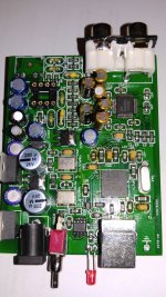
I have a cheap Chinese USB dac with Xmos chip and AK4490EQ, I would like to modify it to act as a USB->Spdif converter, did someone tried something like this before?
What do I need to look for? where to start? and how to do it?
I know it's a long shot....but maybe someone can figure it out.
I'll appreciate any help from you.
Attachments
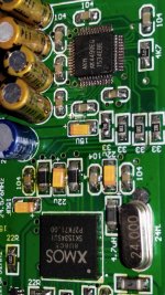
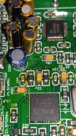
1. Desolder the 33R I2S resistors
2. Get a WM8804 I2S -> SPDIF board (usually available as Raspberry Pi digital output boards)
3. Solder three wires (plus a few ground lines) from the exposed pads to the second board.
You need the three lines towards the board edge. The fourth trace is MCLK, which is not needed for the WM8804. You can work out which is which from the 4490 datasheet. The one closest to the dot is BCK. On the 8804 board you'll have to take a look at the Pi datasheet and you should be able to see which pin is which.
- Status
- This old topic is closed. If you want to reopen this topic, contact a moderator using the "Report Post" button.