Metallized polyphenylene sulphide, these might be ok for power decoupling. They don't show impedance vs. frequency curve which bothers me. This sulphide material is not so hot for audio signals and low voltage film normally don't sound so good. ")
I'll stick with ceramics, oscon and lowesr tantalum for power bypassing. Some sample would be nice to prove if they ok.
I'll stick with ceramics, oscon and lowesr tantalum for power bypassing. Some sample would be nice to prove if they ok.
Optimum Decoupling of Digital
Dear jewilson,
I agree your comment, if U choose OS-Con, unless U change to Blackgate non-polar. NIL will better than that.
Do U know that Dell server Grade display card also use OS-con.
Thanks for your comment for my PCB, KITS.
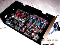
pls see the photos.
I combined use OS-Con, panasonic pureism & Elna non-polar in my tda1541a kits already.
Pls see the full funish photos.
thnaks
thomas
Dear jewilson,
I agree your comment, if U choose OS-Con, unless U change to Blackgate non-polar. NIL will better than that.
Do U know that Dell server Grade display card also use OS-con.
Thanks for your comment for my PCB, KITS.
pls see the photos.
I combined use OS-Con, panasonic pureism & Elna non-polar in my tda1541a kits already.
Pls see the full funish photos.
thnaks
thomas
Attachments
Guido & Jim
Guido & Jim,
Thanks for your views. As previously stated, my idea is to copper pour the back side of the PCB and tie this to the ground plane to shield between the different signal lines.
- The use of lots of vias would ensure the daisy chain effect was minimised since each island would be directly connected to the top ground plane.
Guido, I have indeed noted that no current flows through isolated copper islands, however....
I have read somewhere (can't remember where) that PCBs with grounds on multiple layers could resonate in high speed applications (a sort of LC resonant circuit I suppose). Such grounds should be tied together in many places. Is there truth to this statement?
dear oli,
MY PCB was computor Monther Board & High Speed Display Crd Monther Board PCB Factory. Maximum Can Support 16 layer compact PCB together.
As your opinions. multiple layers could resonate in high speed applications (a sort of LC resonant circuit I suppose). Such grounds should be tied together in many places.
My PCB DID Already. This method is more complication in ground all togethers as a ground plate. But Very quickly ground with low noise. But bigger improvement is REAL Gold Plated in all the path to more smooth the surface for electron to pass away. I also did already in ALL my TWIN TDA1541A PCB for KIT use.
thanks
thomas
.multiple layers could resonate in high speed applications (a sort of LC resonant circuit I suppose). Such grounds should be tied together in many places. Is there truth to this statement?
MY PCB was computor Monther Board & High Speed Display Crd Monther Board PCB Factory. Maximum Can Support 16 layer compact PCB together.
As your opinions. multiple layers could resonate in high speed applications (a sort of LC resonant circuit I suppose). Such grounds should be tied together in many places.
My PCB DID Already. This method is more complication in ground all togethers as a ground plate. But Very quickly ground with low noise. But bigger improvement is REAL Gold Plated in all the path to more smooth the surface for electron to pass away. I also did already in ALL my TWIN TDA1541A PCB for KIT use.
thanks
thomas
Attachments
 to produce PCBs.
Oli,
As U said,
Actually, PCB with grounds on multiple layers could resonate in high speed applications. Real, U right.
second, Such grounds should be tied together in many places.
Right, But sort them together with multiple layers PCBs can short the length of ground. Quickly ground had a result is the background will quite slient.
Oli, my English is not so good. I hope U will understand what I mean. I only like to share the experiences to U that I received in my PCB making that I can suggest to U.
Especially in the enclose material, can lower the noise in digital circuit, this is experience result from the factory.
If I make U unhappy, I say sorry for this.
thanks
thomas
As U said,
I have read somewhere (can't remember where) that PCBs with grounds on multiple layers could resonate in high speed applications (a sort of LC resonant circuit I suppose). Such grounds should be tied together in many places. Is there truth to this statement?
Actually, PCB with grounds on multiple layers could resonate in high speed applications. Real, U right.
second, Such grounds should be tied together in many places.
Right, But sort them together with multiple layers PCBs can short the length of ground. Quickly ground had a result is the background will quite slient.
Oli, my English is not so good. I hope U will understand what I mean. I only like to share the experiences to U that I received in my PCB making that I can suggest to U.
Especially in the enclose material, can lower the noise in digital circuit, this is experience result from the factory.
If I make U unhappy, I say sorry for this.
thanks
thomas
Dear jewilson,
PCB factory told me that gold plate really good. Signal run more smooth. They test in hifU know data is data, as I said, can U told me why graphit carbonate can made the digital data run fast speed will less error. Enclose by graphit carbonate PCB can run very stable & smooth. NObody will know, why intel coming i925X,DDR2 ram all high speed display card need use this type enclose to make PCB.
May be there will some unknown reason but we did not know.
I trust my friend becauase he make PCB, computor PCB monther board, Dispaly card. IBM, Accuphase PCB also his client.
If as U said not need gold plated, I will not agrue with U because I don't know. but I saw although low speed CPU, GPU below 2.4Ghz all need gold plate.
pls see my friends company.
www.2themax.com.
He sell many computor products.
this is my opinions.
thanks
thomas
Graphite carbonate might make a very good substrate or pcb material. FR4 material for a PCB is not the best thing in the world that for sure. I know some people that make pcb's out of Teflon but that a night mare to repair and solder but the capacitance is low.
Did you know that a lot of the very old HP test equipment had Gold plated PCB’s? They stopped that along time ago and they claimed it was no advantage. I have an older distortion analyzer that has gold PCB and even Threshold amp that has Gold pcb you might ask Nelson about that.
Also, the reflow of tin dose not add to the performance of a pcb bare copper is better. The Solder mask type too can affect performance.
[Did you know that a lot of the very old HP test equipment had Gold plated PCB’s? They stopped that along time ago and they claimed it was no advantage. I have an older distortion analyzer that has gold PCB and even Threshold amp that has Gold pcb you might ask Nelson about that.
-----------------------------------------------------------------------------------
Accuphase units have gold plated boards.
-----------------------------------------------------------------------------------
Accuphase units have gold plated boards.
Optimum Decoupling of digital ICs
Dear jewilson,
let talk about the Graphite carbonate enclosure. The factory only told me that this material will not catch any electric stastic . This is the reason that can lower the error during High speed digital signal running. Pls considerate the coming I925X is 1066/ approx 1G FSB.
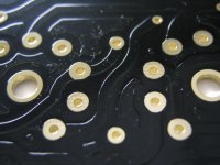
About the gold plate. I would like to tell U there will had different type of Gold plated method. Some is not plated real gold. some may be 18K,20K 22K 24K.
My PCB is 24K gold plated. Its very thin, only 1 micron. Pls know that the gold plate & the Graphite Carbonate will cost me 25% more than the lead trim/coated. I was a diyers. I know diyers heart. We did not satify standard consumer products. May be we like tailor made more. But it cost more money. Me too. But now I can use reasonable money but can produce very good quality goods which benefit to more diyers. Hope U will understand what I say!!!!
About FR4 is a standard of PCB. I PCB also FR4 grade but 2.1mm thickness. which can resist the vibration.
This is the best what I can do in reasonable price.
jewilson,
I think U will know that the OS-con, Elna Gold Brand, MBR160diode. Panasonic OFC lead out pureism Cap.
IRC non-inductive Resisters, Dale ERO all were expensive in EURO & America. Dell server grade PCB also use OS-con for their GPU used.
MY kit only USD 200 supply for all this type parts. May be USD 200 U can only buy parts in USA. The PCB (three pieces) approx Free of charge to U. Pls know that I was not selling parts kits to maintain my life. I was a senior civil servant.
More diyers happy, i happy. This is my Hobby. pls considerate.
I also the Japan Tango, Tamura, Hashimoto, James, Daburu permalloy Output transformer authorized dealer & reseller in Hong Kong.
Parts is Sanyo OS-Con, Elna, BlackGate, RMA, Dale Vishey,IRC.
This is why I can sell them in a very good price. I was the dealer. I can calculate all the expense. I not need middle man charge.
The Result is good news for a very good price to all diyers.
for more detail information.
pls email to me.
thomas@diyaudiocraft.com
thanks
thomas
Dear jewilson,
let talk about the Graphite carbonate enclosure. The factory only told me that this material will not catch any electric stastic . This is the reason that can lower the error during High speed digital signal running. Pls considerate the coming I925X is 1066/ approx 1G FSB.
About the gold plate. I would like to tell U there will had different type of Gold plated method. Some is not plated real gold. some may be 18K,20K 22K 24K.
My PCB is 24K gold plated. Its very thin, only 1 micron. Pls know that the gold plate & the Graphite Carbonate will cost me 25% more than the lead trim/coated. I was a diyers. I know diyers heart. We did not satify standard consumer products. May be we like tailor made more. But it cost more money. Me too. But now I can use reasonable money but can produce very good quality goods which benefit to more diyers. Hope U will understand what I say!!!!
About FR4 is a standard of PCB. I PCB also FR4 grade but 2.1mm thickness. which can resist the vibration.
This is the best what I can do in reasonable price.
jewilson,
I think U will know that the OS-con, Elna Gold Brand, MBR160diode. Panasonic OFC lead out pureism Cap.
IRC non-inductive Resisters, Dale ERO all were expensive in EURO & America. Dell server grade PCB also use OS-con for their GPU used.
MY kit only USD 200 supply for all this type parts. May be USD 200 U can only buy parts in USA. The PCB (three pieces) approx Free of charge to U. Pls know that I was not selling parts kits to maintain my life. I was a senior civil servant.
More diyers happy, i happy. This is my Hobby. pls considerate.
I also the Japan Tango, Tamura, Hashimoto, James, Daburu permalloy Output transformer authorized dealer & reseller in Hong Kong.
Parts is Sanyo OS-Con, Elna, BlackGate, RMA, Dale Vishey,IRC.
This is why I can sell them in a very good price. I was the dealer. I can calculate all the expense. I not need middle man charge.
The Result is good news for a very good price to all diyers.
for more detail information.
pls email to me.
thomas@diyaudiocraft.com
thanks
thomas
Thomas,
I have worked on some of the fastest equipment made, stuff running a teraHz and we have managed just fine with out graphite carbonate enclosure. I not say it may not help or has some advantage it has not made it on to the commercial world of ultra high speed communication equipment. So the question is why then do I need it, will it raise cost's, improve RF issues unlike some people on the forum I don't know the answers to this and admit it. If you have any technical information on graphite carbonate enclosure why don’t you post it?
Regarding FR4, while it is a strong material and use my almost every one, it is not the best performance material for PCB's. Having said that, it works well it is cost efficient and is accepted in the industry.
Optimum Decoupling of digital ICs
Dear jewilson,
fully understood already.
I had not any detail information about this material.
THis is the computor PCB factory engineer told me & advise me that use this material will benefit to digital signal fast running.
As U said. U working in the fastest equipment made, stuff running a teraHz company. Our DAC will less less less lower speed than your fast equipment. But, Jewilson, I was a diyers, not a merchant. Diy was not my business. If my friend can supply this top material in their base price. why I not choose it.
When the factory told me about this material, they still testing some 128Bit Display card. They said some of the reason they still did not understand was why run in high speed diaplay card was easy cause error that use traditional material. So they choose this material & get a good result. If i had more information. I will immediately post to forum.
But as The factory said. The coming PCB of i925x chips & more High speed GPU will choose this material to enclose or mix this material to enclose the PCB. My PCB only use a thin enclose material so quite thin but I choose High density graphite carbonate enclosure. I only hope to produce (BOB) Best of Best items to all diyers. This PCB was only small % of the kit. The large % is the Dale, CGW, pureism, elan & OS-con. All I must wire-transfer money to order from japan, pay postage,. bank charge & will effect by the rate of japan Yen.
Although I was the dealer of this product in hong kong. I still had some problems need to fix. is it right????
But the PCB factory was my friends.He also a diyer use lowther TP-1, PX25 SE amp. He know Diyers desire. He OEM this PCB to me hadn't earn any money!! pls considerate.
Otherwise I cannot sell the kits in low price but extra high quality parts.
I know the FR4 is not the best for PCB. But I choose is OFC audio grade FR4 PCB's. This PCB is request by japan's audio company for OEM their PCB's. Not standard FR4. standard is 1.6mm.
This PCB is OFC copper foil & 2.1mm thick of the PCB with 1 micon gold plate( real gold).
hope U will consent my condition.
thanks
thoams
Do I understand this correctly?
I am about to etch a PCB for my DAC (at last)- but after a quick recheck of my schematic I have discovered a possibility for simplifying things a little more around the CS8412....
Previously.. (copied verbatim from other DIY published designs!)
Pin 6 C0/E0 bar = High
Pin 13 CS12/FCK = High
Pin 16 SEL = High
The above arrangement provides 'status information' in 'consumer mode' format on the status/error pins e.g. frequency and demphasis information.
I do not need this information as these pins are not connected in my simple digital filterless non-oversampling DAC.
My new idea..
Pin 6 C0/E0 = disconnected (since this is now an output)
Pin 13 CS12/FCK = Low
Pin 16 SEL = Low
This new arrangement will provided error information (as errors occur) on the status/error pins. Again, I do not need this information, but on my PCB I can simply tie these pins to my ground plane and reduce complexity a little.
I have seen some references on the Web to putting the CS8412 into 'consumer mode'. This would seem to imply that 'consumer mode' is required for the CS8412 to decode data from a standard consumer CD player. If you read the data sheet for the CS8412 carefully, the 'consumer mode' determines the nature of status information relayed on the status/error pins (which I don't care about).
My question....
Is this correct?
Can anyone with experience forsee problems with my new arrangment? (e.g. effect on sound quality)
Sorry if any of this seems blindingly obvious. Perhaps I am simply slow in my understanding of the data sheet!
Errors come and go, and the leds may not be on long enough for you to even know there was an error. So you want to use errors then you might need to add a one shot or add some D flip flops so the led is lit long enough to see it.
Personally, I don't care much for these idiot lights they don't do any thing for the sound. Also, you will know if the CD has errors you will here it. Just run the signal to some test berg pin and when you don’t have anything better to do you can connect them
.
Personally, I don't care much for these idiot lights they don't do any thing for the sound. Also, you will know if the CD has errors you will here it. Just run the signal to some test berg pin and when you don’t have anything better to do you can connect them
.
- Status
- This old topic is closed. If you want to reopen this topic, contact a moderator using the "Report Post" button.
- Home
- Source & Line
- Digital Source
- Optimum Decoupling of Digital ICs