Hi all,
I am newbie here and I need your help. I've purchased a Rotel RCD855 from a museum sale. Plugged it on with a CD, the machine is reading the TOC. All the buttons functions work, but there is no sound from neither Analog or Digital output.
Can you help me to diagnose the problem and fix it please?
Thank you very much,
Napo
You say it reads the TOC, but does it actually Play? ie, does the Time 'tick' along?
Have you any Electronics experience, what Test Gear have you available?
Service Manual here.................
Rotel RCD-855 Manual - Stereo Compact Disc Player - HiFi Engine
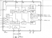
Looks like it uses the TDA1541 DAC IC, nice, are you able to oscilloscope the DATA and Clocks going into this IC?
It has several Power Supplies, can you measure these with a DVM for us?
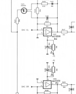
The Analogue then goes into two Op-Amps, U401/U402, these are fed by +/-15V, can you check these? I think the problem will lie elsewhere though as you say the Digital Out is not working also.
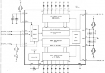
This is derived from U (108?) (The Manual isn't scanned very well) the SAA7220 Pin 16. Can you measure the Supplies and DATA/Clocks on this IC?
P.
Have you any Electronics experience, what Test Gear have you available?
Service Manual here.................
Rotel RCD-855 Manual - Stereo Compact Disc Player - HiFi Engine
Looks like it uses the TDA1541 DAC IC, nice, are you able to oscilloscope the DATA and Clocks going into this IC?
It has several Power Supplies, can you measure these with a DVM for us?
The Analogue then goes into two Op-Amps, U401/U402, these are fed by +/-15V, can you check these? I think the problem will lie elsewhere though as you say the Digital Out is not working also.
This is derived from U (108?) (The Manual isn't scanned very well) the SAA7220 Pin 16. Can you measure the Supplies and DATA/Clocks on this IC?
P.
Hi,
Thank you Percival for your input.
- Yes the tracks are working with time counting along on the display.
- I am a newbie DIY and I have only a Multimeter with me now.
- I never use the oscilloscope yet, and I dont know what can it do, but I can try to buy local one
- I will try to find from the service manual and will back to you, hope you will continue to help me.
Thank and regards,
Hi Percival,
I am reading the Service manual to find the supplies to the U108. The scanned SM is too dimmed that I cannot understand or guess what it is.
Could you tell me which pins are the supplies? I attached the scanned U108 here for your reference.
Thank you for continue helping me. I am really interested to find out and learning this CDP.
Napo
Attachments
I've just measured the voltage between pins 2-3 of the U401, U402. They both show 0V, either AC or DC.
- Are the pins 2 and 3 the supply voltage for the U401, U402?
- I see they have 6 pins, but on the manual only 4 pins (1-4). Do I miss smth?
- Can you tell me how to check the supply of TDA1541 and SAA7220, how much the voltage should be?
Thank you and please keep update.
- Are the pins 2 and 3 the supply voltage for the U401, U402?
- I see they have 6 pins, but on the manual only 4 pins (1-4). Do I miss smth?
- Can you tell me how to check the supply of TDA1541 and SAA7220, how much the voltage should be?
Thank you and please keep update.
I've just measured the voltage between pins 2-3 of the U401, U402. They both show 0V, either AC or DC.
You will not measure anything with a Meter here, these are the inputs of the IC. They are NE5532's which are 8 Pin IC's. Their Supply Pins are 4 (Negative Supply) and 8 (Positive Supply). You should expect Pin 4 to be -15Volts and Pin 8 to be +15Volts.
- Are the pins 2 and 3 the supply voltage for the U401, U402?
- I see they have 6 pins, but on the manual only 4 pins (1-4). Do I miss smth?
- Can you tell me how to check the supply of TDA1541 and SAA7220, how much the voltage should be? The SAA7220 looks like it has only one supply, on Pin 24 which should be +5Volts. The TDA1541 has several Supplies.
Pin 15 = -15V
Pin 26 = -5V
Pin 27 = +5V
Thank you and please keep update.
If you can check those Voltages and report back, that'll be a start. If you could also check the Voltage on the KILL line. The Bases of the Muting Transistors. If these are being turned on then that would produce no O/P.
After that we really need to see what sort of signals are present and that would involve an oscilloscope I'm afraid.
P.
Hi,
I have measured some supplies:
U401 and U402 (NE5532)
- Pin 4: -15v
- Pin 8: +15v
U301 (TDA1541)
- Pin 1: +2.5v, while the manual says +5v
- Pin 15: -15v
- Pin 26: -5v
- Pin 27/28: +5v
U 108 (SAA2720)
- Pin 24: +5v
So the only difference to the manual is the pin 1 of TDA1541 which is only +2.5v
Please advise, thank you!
Pin 1 of the TDA1541 is connected to +5V via a 3k9 resistor to add a little bias to the Left/Right Clock (WSBD) the +2.5 is probably OK.
You won't measure anything with a DVM at the Output Terminals I'm afraid.
The 8.8V on the middle Pins of the Muting Transistors doesn't seem right to me. The Middle Pin on a BC.... Transistor is (usually) its Base. So, with 8.8V there the Transistors are ON and will be shorting the Signal (on the Collectors) to 0Volts (the Emitters). So, where's that 8.8V coming from?
The Bases are held negative during normal operation by the -15V via R807 ((?)The Manual is hard to read)). My favourite suspicion would be the little circuit at the top left of the page with the TDA1541 on, page 13. That looks like a (rather complicated) Initial Power On Mute which will Mute the O/P on Turn On to stop any Pops when Power is applied.
If you know how to measure Transistors with your DVM then I'd measure all those in that little circuit. If you're not sure, then to prove a point, I'd remove T802. With the Volume down on your Amplifier, turn on the Rotel and see what happens when you raise the Volume gently.
P.
Hi Percival,
- When I measured the voltage, I always turn the CD on, put the lead - of my DVM to the Negative pin on the analog output, as the ground. I dont know if it is right.
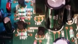
Thank you very much for your finding. I retrace the little circuit you mentioned and found out that the T801 is missing. I dont know what happened to it, it must have been removed by previous owner? Pls see the picture for detail.
I measured the T802, T803, T804 with the DVM:
T801: missing
T082: Lead - on the Base (middle): two other pins read 33Mohm, 60Kohm
Lead + on the Base: 8M, 55K
T803: Lead - on Base: 160K, 5M
Lead + on Base: 160K, 100K
T804: Lead - on Base: 5M, 5M
Lead + on Base: 1M, 1M
I measured also the T403 - T406:
T403: - on Base: 80K, 60K
+ on base: 80K, 60K
T404: - on base: 80K, 50K
+ on Base: 70K, 50K
T405: - on base: 70K, 50K
+ on base: 70K, 50K
T406: same to T405.
Your advices pls.
- When I measured the voltage, I always turn the CD on, put the lead - of my DVM to the Negative pin on the analog output, as the ground. I dont know if it is right.
Thank you very much for your finding. I retrace the little circuit you mentioned and found out that the T801 is missing. I dont know what happened to it, it must have been removed by previous owner? Pls see the picture for detail.
I measured the T802, T803, T804 with the DVM:
T801: missing
T082: Lead - on the Base (middle): two other pins read 33Mohm, 60Kohm
Lead + on the Base: 8M, 55K
T803: Lead - on Base: 160K, 5M
Lead + on Base: 160K, 100K
T804: Lead - on Base: 5M, 5M
Lead + on Base: 1M, 1M
I measured also the T403 - T406:
T403: - on Base: 80K, 60K
+ on base: 80K, 60K
T404: - on base: 80K, 50K
+ on Base: 70K, 50K
T405: - on base: 70K, 50K
+ on base: 70K, 50K
T406: same to T405.
Your advices pls.
Attachments

Sorry, can you measure the Voltages around that little circuit?
I am concerned about T801 being missing. From the solder side does it look as if it was fitted and removed or never fitted? If removed, that makes me wonder what else may have been removed/replaced, possibly incorrectly.
P.
I am concerned about T801 being missing. From the solder side does it look as if it was fitted and removed or never fitted? If removed, that makes me wonder what else may have been removed/replaced, possibly incorrectly.
P.
Hi,
Here is the little circuit. I think its input voltage is AC. I check the board at the T801 and it seems that it was never fitted there.
- I measured the DC at all the 3 pins of T802, all show 3.5V.
If I take the AC at that 3 pins with the Negative output, all show 5V
- I measured the DC at the board (missing the T801), all show 0.25v
If the AC, they all show 0.5v.
Thank for your help
Attachments
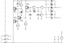
We're not bothered by AC after the series of Diodes D803-806 as these convert the AC to DC which the Circuit operates on.
Without T801 there is very little point in the rest of the circuit as its only point of contact with 'the outside world' is T801's Collector.
Perhaps fit one and see what happens! I really don't think it will help though.
You now say you have 0.25V DC on the Tracks where T801 is however, previously in post 11 you said you had 8.8V DC on the Muting Transistors. Can you confirm you have 0.25V DC on the Tracks of T801 and that you have 8.8V DC on the middle Pins of T403/4/5/6? It's a difficult Scan of a Manual to read but as far as I can make out there is only a 1k5 resistor in between these two points so I am wondering where the 8.8V DC on the Muting Transistors is coming from.
P.
Hi Percival and Willi,
Thank you for continuing help.
Percival, I check the tracks of T801, it has 4 traces as you see on photo. The one lowest and the 2 left show 3.8V DC, the one on the far right show 0V. But if I press the DVM lead harder, it show sometime 23v.
Yes, the T403, T404, T405, T406 middles show -8.8V
Willi, thank for your advice. I will try if I can do what you said.
Regards
Attachments
- Status
- This old topic is closed. If you want to reopen this topic, contact a moderator using the "Report Post" button.
- Home
- Source & Line
- Digital Source
- Rotel RCD855 no output