Hi,
Hard to have any idea without picture and/or shematic. Is there any space for improvement ? Do you want to ack the output signal on a different board ? Or just swap some parts ?
The USB front end is a little out dated (jitter). Diying on the I/V can be limited because of that... And just give you a different color/presentation only !
You have certainly an active buffer after your passive I/V ?!
1794 chip is still a good dac chip. You can have a look at the thread from George around the AD844 for instance. http://www.diyaudio.com/forums/digital-source/227677-using-ad844-i-v.html
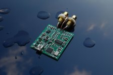
Schematics will be difficult to produce, since I made too many changes to pcb layout without back annotation, so now I have an orphaned pcb layout. But it's similar to pupdac, only with all smd construction and +-4.75v at the active buffer at the output. Jitter should not be the issue as Pcm2707 uses external 25pps oscillator?
DAC sounds good but not good enough. I thought that i/v stage could use some improvements, as 1794 datasheet suggests.
Sent from my NX506J using Tapatalk
DAC sounds good but not good enough. I thought that i/v stage could use some improvements, as 1794 datasheet suggests.
Sent from my NX506J using Tapatalk
If money not an issue, just for experiment (sometimes it's less expensive to buy a better dac ") ...) :
...) :
You can work on the powersupply
you can swap the i/v resistor if the dac chip is in passive i/v conversion by : smd Sussumu very low noise thin film or special smd RF resistor (Mouser, Digikey, Farnell, etc)...
Change some caps in buffer stage to coock a little the sound, etc.
But better improvements come mainly from a better pcb layout and parts BOM with sota supplies (they call that: the Design). Tweaking a little can helps you to improve the sound and coocks it in relation to the rest of the whole hi-fi (which is important) and some time there is good margin enough. The front end is also of a first importance but it's difficult without quality issue to glue for instance an external USB to I2S before the dac chip and I don't advise it to you but if you redraw the dac chip pcb to allow it by sota connexions.
Again you can try to ack th eoutput and go for active I/V with integrated chip with proved design (GeorgeHifi AD844 worths really a reading for instance)
But also many good (semi)diy DACs enough these days : JLSound. here on DIYAUDIO also with ESS or AK dac chips. Many good USB to I2S front end. Or the DDDAC with the same chip as you have... the earth is ALWAYS a good clock design, and most of the diy dac miss that, even here on DIYA but few projects IMO. And here the improvements are radical for the sound quality (reclocking, buffering, low phase noise clock, low noise supply...)
Just a simple point of view to try to answer to your question... all is question of goal and money, but for the fun of it you should try
With some photographs some experienced technicians (I'm not) may help you (I learned a little like that) but too large question equal less precise answer.
I tryed, I hope that helps... good luck
...) :You can work on the powersupply
you can swap the i/v resistor if the dac chip is in passive i/v conversion by : smd Sussumu very low noise thin film or special smd RF resistor (Mouser, Digikey, Farnell, etc)...
Change some caps in buffer stage to coock a little the sound, etc.
But better improvements come mainly from a better pcb layout and parts BOM with sota supplies (they call that: the Design). Tweaking a little can helps you to improve the sound and coocks it in relation to the rest of the whole hi-fi (which is important) and some time there is good margin enough. The front end is also of a first importance but it's difficult without quality issue to glue for instance an external USB to I2S before the dac chip and I don't advise it to you but if you redraw the dac chip pcb to allow it by sota connexions.
Again you can try to ack th eoutput and go for active I/V with integrated chip with proved design (GeorgeHifi AD844 worths really a reading for instance)
But also many good (semi)diy DACs enough these days : JLSound. here on DIYAUDIO also with ESS or AK dac chips. Many good USB to I2S front end. Or the DDDAC with the same chip as you have... the earth is ALWAYS a good clock design, and most of the diy dac miss that, even here on DIYA but few projects IMO. And here the improvements are radical for the sound quality (reclocking, buffering, low phase noise clock, low noise supply...)
Just a simple point of view to try to answer to your question... all is question of goal and money, but for the fun of it you should try
With some photographs some experienced technicians (I'm not) may help you (I learned a little like that) but too large question equal less precise answer.
I tryed, I hope that helps... good luck
Last edited:
Well, thanks for comprehensive answer If you weren't lazy to write all that up., I shouldn't be lazy to draw a schematics from scratch, and draw the missing components along the way
So here it is, only with AD1852 instead of PCM1794. I will build this one and see how they compare - AD1852 has I/V built in, so no room for improvisation
I could use some sanity check for AD1852 pin connections, I haven't used it before at all. Not sure for example if I should pull pins 192/48 (7) and 96/48 (10) somewhere.
If you weren't lazy to write all that up., I shouldn't be lazy to draw a schematics from scratch, and draw the missing components along the waySo here it is, only with AD1852 instead of PCM1794. I will build this one and see how they compare - AD1852 has I/V built in, so no room for improvisation
I could use some sanity check for AD1852 pin connections, I haven't used it before at all. Not sure for example if I should pull pins 192/48 (7) and 96/48 (10) somewhere.
Attachments
Last edited:
Did you think to remove at the DC input Voltage bus/line (5 v usb) the resistor and input a clean low noise external supply at the + pin of C7 instead ? (gnd wire (-) : on the gnd aera of the c7 cap to the (-) of the cell.)
Is there some cheap 5V LiPo external cell for smartphone for instance (15 euros!)! Improving C7 maybe (if not smd cap)...
because 5V coming from usb bus is always crappy due to smps into the PC !
Does it Worth... I don't know, it's up to you...
Here it looks like a better design but less diy : Products - I2S over USB Audio look at the first of the list !
If you're someone who cares about how your DAC sounds, pay attention to the loading you place on the DAC chip's outputs. In my experience, single digit kohms is too low to get best dynamics from CMOS opamps.
You can scale the impedances of your output filter (up the Rs, down the Cs by the same factor) - you might want to go to JFET input though to keep the thermal noise under control.
You can scale the impedances of your output filter (up the Rs, down the Cs by the same factor) - you might want to go to JFET input though to keep the thermal noise under control.
I was thinking about battery power earlier, but need to test first if I could hear any actual improvement on sound compared to emi filtered usb power with LDO regulators on every pin. If yes, then I was thinking about using LiPo battery charger with a switch to charge battery while music is not playing, while powering the DAC from battery when there is audio signal.
But if it is to learn and have fun when the surounding mods become more expensive than the dac module itself, better to buy a better dac module !
An exception to this rule is when the layout is already very good, so one point or two can be improved. But a good layout comes always with the dedicated parts to make it, so often : not too much headroom to wait for ! But you always improve Something or make it closer to your taste or the rest of the Hifi for a better match.
Luckily here, it's a cheap one ! With a good dac chip !
Photographs ?
Last edited:
The schematic in this link works really well. It's shown for a pcm1798, you have to adapt it for the higher currents of a 1794 (see the links in the post for that).
A good alternative ime is an opa1632 based I/V but, as you need to provide a buffered voltage reference or a servo to the opa1632's vcom pin, it's a bit more involved.
A good alternative ime is an opa1632 based I/V but, as you need to provide a buffered voltage reference or a servo to the opa1632's vcom pin, it's a bit more involved.
- Status
- This old topic is closed. If you want to reopen this topic, contact a moderator using the "Report Post" button.
- Home
- Source & Line
- Digital Source
- Best I/V stage for USB dac