dddac, thanks for the posts ...
My experience with Asynchronous Sample Rate Converters includes architecture, design, test & measurement of silicon implementations, as well as limited personal use in audio equipment. It's my intention with this thread to describe the technical details of how they work, and provide a performance comparison to PLL-based clock recovery schemes. And I welcome any feedback about how they sound")
I have no direct experience with the dddac1543. But your measurements of the various audio spectra look quite puzzling. The effects of Asynchronous Rate Conversion, implemented in devices like the CS8420 & the AD1896, are particularly easy to measure, and should not vary THAT dramatically from DAC to DAC ... for the simple reason that any DACs in question will be clocked by a local, ultra-clean crystal oscillator in the ASRC environment, so any varying jitter-sensitivities between DACs will be completely eliminated. Which, of course, leaves only the audio band data. Why would two DACs, each clocked by an ultra-clean clock, have such dramtically different responses to the same audio band data, and hence the same audio band input spectrum? I suggest the problem is not in the ASRC.
But please allow me to ask some questions for clarification :
1. Just to make sure, you are referring to Asynchronous Sample Rate Conversion, and not simply Asynchronous Re-Sampling, correct? I know you mentioned the CS8420, which does indeed perform Asynch Rate conversion ... that is, re-calculating the correct audio output samples that correspond to the new time points.
2. Were the observations you made ... namely, different DACs responding differently to the rate-converted data ... driven by the same data, at the same time? I ask because I know the CS8420 has had it's share of bugs & glitches over the years.
Again, the time base for the DACs is ultra-clean in an ASRC environment, which leaves ONLY the baseband data itself, and it's corresponding audio spectrum, to "misbehave". If one DAC processes this baseband data accurately, and another doesn't ... I would look to the DAC rather than the ASRC.
And a digital filter such as the DF1704 should have no effect (or at least, very minimal) on the baseband audio spectrum ... again, the clocks for the filters & DACs are ultra-clean, so clocking is removed as a variable.
If you guys find this explanation unconvincing, I'm wide open to any theories that would explain the TERRIBLE performance displayed in dddac's spectra, that would implicate the ASRC ... ???
My experience with Asynchronous Sample Rate Converters includes architecture, design, test & measurement of silicon implementations, as well as limited personal use in audio equipment. It's my intention with this thread to describe the technical details of how they work, and provide a performance comparison to PLL-based clock recovery schemes. And I welcome any feedback about how they sound
I have no direct experience with the dddac1543. But your measurements of the various audio spectra look quite puzzling. The effects of Asynchronous Rate Conversion, implemented in devices like the CS8420 & the AD1896, are particularly easy to measure, and should not vary THAT dramatically from DAC to DAC ... for the simple reason that any DACs in question will be clocked by a local, ultra-clean crystal oscillator in the ASRC environment, so any varying jitter-sensitivities between DACs will be completely eliminated. Which, of course, leaves only the audio band data. Why would two DACs, each clocked by an ultra-clean clock, have such dramtically different responses to the same audio band data, and hence the same audio band input spectrum? I suggest the problem is not in the ASRC.
But please allow me to ask some questions for clarification :
1. Just to make sure, you are referring to Asynchronous Sample Rate Conversion, and not simply Asynchronous Re-Sampling, correct? I know you mentioned the CS8420, which does indeed perform Asynch Rate conversion ... that is, re-calculating the correct audio output samples that correspond to the new time points.
2. Were the observations you made ... namely, different DACs responding differently to the rate-converted data ... driven by the same data, at the same time? I ask because I know the CS8420 has had it's share of bugs & glitches over the years.
Again, the time base for the DACs is ultra-clean in an ASRC environment, which leaves ONLY the baseband data itself, and it's corresponding audio spectrum, to "misbehave". If one DAC processes this baseband data accurately, and another doesn't ... I would look to the DAC rather than the ASRC.
And a digital filter such as the DF1704 should have no effect (or at least, very minimal) on the baseband audio spectrum ... again, the clocks for the filters & DACs are ultra-clean, so clocking is removed as a variable.
If you guys find this explanation unconvincing, I'm wide open to any theories that would explain the TERRIBLE performance displayed in dddac's spectra, that would implicate the ASRC ... ???
We may be in for a long thread .... But let's move forward !
So, we have a situation where we need to digitally CALCULATE output data samples at new points in time, different than the input data time points. And the time points are NOT synchronized ... so there is no finite integer interpolation that we can perform on the input data that will align perfectly with the output time points we need.
Well who says we need "perfect" time alignment? I know I can't hit the output time points EXACTLY through integer interpolation, meaning that no integer interpolation of the input data on the Fs_in chart will provide the exact audio samples that correspond precisely to the exact points, in time, on our Fs_out chart. BUT, I can get arbitrarily close This is the essence of ASynchronous Sample Rate Conversion.
So here's what I'm going to do. Conceptually, I will interpolate the input data by a pretty huge number (we'll be more specific very soon) ... in fact, by a pretty huge INTEGER number, so that I effectively "fill in" very many samples in-between the original Fs_in samples. I know, because we're talking asynch, that when an output "tick" comes along at Fs_out, I will not be able to provide an interpolated input sample that corresponds to that exact point in time ... so what if I just provide the most recently interpolated sample that I calculated instead? How BIG will the error be?
It's the nature of ANY bandlimited signal that, the more I interpolate the data ... or "fill in" data points between the original Nyquist points ... the LESS difference there will be between samples. And in fact, the more I interpolate, the smaller the error will be, by choosing the WRONG sample .... !!!!
I know how disturbing this sounds. But we must remember a couple things : One, a bandlimited signal is NOT free to do whatever it pleases between Nyquist samples ... in fact, it's pretty smoothly varying between those samples. And two, the more samples we can calculate beyond the Nyquist rate, through a very accurate interpolation process, the more adjacent samples will look the same. These are simple, indisputable facts of life
But no matter what, grabbing the most recently calculated interpolated sample, instead of the exact sample required at Fs_out, will introduce error. The question is ... How far do I have to interpolate, by what integer, so that grabbing the most recent sample will give me acceptably LOW error ??? We can never achieve perfection here, but we can get ARBITRARILY CLOSE ... simply because the higher I interpolate, the lower the error
Let's pause for questions This is a big point to digest. Next post will fully develop the conceptual model, and provide a way to calculate the error from "grabbing the most recently interpolated sample" when an Fs_out tick comes along.
But let's move forward !So, we have a situation where we need to digitally CALCULATE output data samples at new points in time, different than the input data time points. And the time points are NOT synchronized ... so there is no finite integer interpolation that we can perform on the input data that will align perfectly with the output time points we need.
Well who says we need "perfect" time alignment? I know I can't hit the output time points EXACTLY through integer interpolation, meaning that no integer interpolation of the input data on the Fs_in chart will provide the exact audio samples that correspond precisely to the exact points, in time, on our Fs_out chart. BUT, I can get arbitrarily close
This is the essence of ASynchronous Sample Rate Conversion.So here's what I'm going to do. Conceptually, I will interpolate the input data by a pretty huge number (we'll be more specific very soon) ... in fact, by a pretty huge INTEGER number, so that I effectively "fill in" very many samples in-between the original Fs_in samples. I know, because we're talking asynch, that when an output "tick" comes along at Fs_out, I will not be able to provide an interpolated input sample that corresponds to that exact point in time ... so what if I just provide the most recently interpolated sample that I calculated instead? How BIG will the error be?
It's the nature of ANY bandlimited signal that, the more I interpolate the data ... or "fill in" data points between the original Nyquist points ... the LESS difference there will be between samples. And in fact, the more I interpolate, the smaller the error will be, by choosing the WRONG sample .... !!!!
I know how disturbing this sounds. But we must remember a couple things : One, a bandlimited signal is NOT free to do whatever it pleases between Nyquist samples ... in fact, it's pretty smoothly varying between those samples. And two, the more samples we can calculate beyond the Nyquist rate, through a very accurate interpolation process, the more adjacent samples will look the same. These are simple, indisputable facts of life
But no matter what, grabbing the most recently calculated interpolated sample, instead of the exact sample required at Fs_out, will introduce error. The question is ... How far do I have to interpolate, by what integer, so that grabbing the most recent sample will give me acceptably LOW error ??? We can never achieve perfection here, but we can get ARBITRARILY CLOSE ... simply because the higher I interpolate, the lower the error
Let's pause for questions
This is a big point to digest. Next post will fully develop the conceptual model, and provide a way to calculate the error from "grabbing the most recently interpolated sample" when an Fs_out tick comes along.Welcome to the forum, werewolf! I look forward to some serious nitty-gritty technical discussion of audio DSP on here...
Not to spoil your lesson, werewolf, and I'm sure you're already aware of this, but there's a nice little discourse on polyphase sin(x)/x filters for async. rate conversion in the AD1890 datasheet... you may wish to refer to it's illustrations... The actual explanations contained in the datasheet will certainly need further clarification for those forum members who are not as familiar with the mathematics and jargon of DSP.
I should think not, though you've got me noodle-scratching now about what windowing function will give the best combination of passband flatness and stopband rejection... hmm. Blackman?
I've been waiting for someone to back me up on this one... I've always known it to be true, but many among the hi-fi crowd seem to have a phobia of some sort regarding FIR filters of the sin(x)/x function, including both oversampling and async. rate conversion varieties. A common argument against sin(x)/x filters is that they cause 'pre-ringing'... obviously somebody simply looked a the impulse response, and declared that such filters were unfit for audio use. Personally, I think the sin(x)/x function is one of the most beautiful pieces of math I've ever worked with. I have some related discussion for you on this topic later... specifically with regard to ripple in the passband (think inverse Fourier)......It will be the ultimate intent of this thread to compare and demonstrate the superiority of this technique to option #1.
Not to spoil your lesson, werewolf, and I'm sure you're already aware of this, but there's a nice little discourse on polyphase sin(x)/x filters for async. rate conversion in the AD1890 datasheet... you may wish to refer to it's illustrations... The actual explanations contained in the datasheet will certainly need further clarification for those forum members who are not as familiar with the mathematics and jargon of DSP.
ALL of the high frequency residual image energy must fold back down during decimation, because it's gotta end up in half the sample rate. Knowing this, what's the best stopband "shape" for the ASRC interpolator? Hint : it's NOT the flat, equi-ripple response you see with most DAC interpolators or ADC decimators. Flat stopband does NOT minimize total stopband energy ... but that's exactly what you need for ASRC.
I should think not, though you've got me noodle-scratching now about what windowing function will give the best combination of passband flatness and stopband rejection... hmm. Blackman?
I'm only familiar with frequency domain in regards to images, which are 2D. The Fourier Transform there is also 2D, with real and imaginary axes, and is often represented, a la Euler, in a frequency and phase coordinate system.
Since the audio signal is 1D, I'm assuming that so is its FT? My question is then, what bearing the phase in an audio signal has on the time/frequency representation.
Since the audio signal is 1D, I'm assuming that so is its FT? My question is then, what bearing the phase in an audio signal has on the time/frequency representation.
hey guys, some great feedback once again Let's address some questions, before we continue :
hifiZen - thanks for the welcome! DSP is a passion of mine Let's address a VERY significant point, still causes endless debate. We need to separate out two issues : pre/post ringing, and pre/post echo. These are two VERY distinct issues, but the distinction is a bit tricky to observe in the time domain.
Pre/post ringing : most obvious in the classic step response of a steep, linear phase (usually FIR) filter. Often thought to be a bad thing, for some reason. But any arguments suggesting that this response is bad, are fundamentally flawed ... certainly a topic for another thread! Let me just say now, for the record, that the pre/post ringing we often encounter in digital audio is nothing more than an artifact of the Gibbs phenomenon ... which simply states that abrupt transitions or discontinuities in one domain, cause ringing in the other. Bandlimited systems unfortunately fit in this category ... and there is no better example of a SHARPLY bandlimited system than digital audio. Don't like the ringing? Sure we can eliminate it ... but the price you pay will be aliasing, pure & simple ... no way around it And that's a BAD tradeoff.
Pre/post echo : Alot more subtle. A duality in the Fourier Transform can be invoked to show that passband RIPPLE ... a non-ideal filtering effect most commonly associated with FIR filters ... causes some slight echo in the time domain (kinda like very, very faint ghosts in analog TV images). This effect is NOT fundamental to digital audio, unlike pre/post ringing above. It can be driven to very low levels with long FIR filters, or avoided altogether with classes of maximally flat IIR, or (VERY long) maximally flat FIR filters. Again, probably a topic for another post! I sure look forward to it
Polyphase filters ... we're gonna talk about these very soon, in this very thread! I'll check into that AD stuff, see if I can find some useful images Shortly we'll introduce the concept of a "Polyphase locked loop" in this very context of Asynchronous Sample Rate conversion. It's the key to understanding how ASRC's respond to jitter
Stopband rejection : Of course, we want a flat passband for any rate conversion. But I've hinted that a flat or equiripple stopband is a very bad choice ... at least in the sense that you can do MUCH better, for the same length FIR filter. What you need for an Asynch SRC is minimal TOTAL stopband energy. Now you can research alot of technical papers about minimizing different "norm" functions in the stopband ... but it turns out that a stopband roll-off (not flat) of just about 6dB per octave will minimize stopband energy Heck I've always maintained that such a stopband shape makes better sense even for DAC interpolation filters, but sometimes it's hard to overcome industry standards Oh well, maybe even yet ANOTHER thread one day
Prune - An audio signal is "one dimensional" in the sense that the time axis has only one dimension. As you pointed out, this is different than, for example, an image signal, because the spatial plane on which images are represented is of course "two-dimensional". However, the Fourier Transform of even a 1-D signal is a COMPLEX function of frequency. Meaning that the Fourier Transform has a magnitude function vs. frequency, AND a phase function vs. frequency (or, alternatively, a REAL function vs. frequency and an IMAGINARY function vs. frequency ... but most people in the audio biz are more comfortable thinking about complex numbers in magnitude/phase form, rather than real/imaginary form... most likely due to the ear's relatively low sensitivity to absolute phase).
Gotta run for a second ... but I'll be right back because I'm not happy with my response to dddac's posts ...
Let's address some questions, before we continue :hifiZen - thanks for the welcome! DSP is a passion of mine
Let's address a VERY significant point, still causes endless debate. We need to separate out two issues : pre/post ringing, and pre/post echo. These are two VERY distinct issues, but the distinction is a bit tricky to observe in the time domain.Pre/post ringing : most obvious in the classic step response of a steep, linear phase (usually FIR) filter. Often thought to be a bad thing, for some reason. But any arguments suggesting that this response is bad, are fundamentally flawed ... certainly a topic for another thread!
Let me just say now, for the record, that the pre/post ringing we often encounter in digital audio is nothing more than an artifact of the Gibbs phenomenon ... which simply states that abrupt transitions or discontinuities in one domain, cause ringing in the other. Bandlimited systems unfortunately fit in this category ... and there is no better example of a SHARPLY bandlimited system than digital audio. Don't like the ringing? Sure we can eliminate it ... but the price you pay will be aliasing, pure & simple ... no way around it And that's a BAD tradeoff.Pre/post echo : Alot more subtle. A duality in the Fourier Transform can be invoked to show that passband RIPPLE ... a non-ideal filtering effect most commonly associated with FIR filters ... causes some slight echo in the time domain (kinda like very, very faint ghosts in analog TV images). This effect is NOT fundamental to digital audio, unlike pre/post ringing above. It can be driven to very low levels with long FIR filters, or avoided altogether with classes of maximally flat IIR, or (VERY long) maximally flat FIR filters. Again, probably a topic for another post! I sure look forward to it
Polyphase filters ... we're gonna talk about these very soon, in this very thread! I'll check into that AD stuff, see if I can find some useful images
Shortly we'll introduce the concept of a "Polyphase locked loop" in this very context of Asynchronous Sample Rate conversion. It's the key to understanding how ASRC's respond to jitter Stopband rejection : Of course, we want a flat passband for any rate conversion. But I've hinted that a flat or equiripple stopband is a very bad choice ... at least in the sense that you can do MUCH better, for the same length FIR filter. What you need for an Asynch SRC is minimal TOTAL stopband energy. Now you can research alot of technical papers about minimizing different "norm" functions in the stopband ... but it turns out that a stopband roll-off (not flat) of just about 6dB per octave will minimize stopband energy
Heck I've always maintained that such a stopband shape makes better sense even for DAC interpolation filters, but sometimes it's hard to overcome industry standards Oh well, maybe even yet ANOTHER thread one day Prune - An audio signal is "one dimensional" in the sense that the time axis has only one dimension. As you pointed out, this is different than, for example, an image signal, because the spatial plane on which images are represented is of course "two-dimensional". However, the Fourier Transform of even a 1-D signal is a COMPLEX function of frequency. Meaning that the Fourier Transform has a magnitude function vs. frequency, AND a phase function vs. frequency (or, alternatively, a REAL function vs. frequency and an IMAGINARY function vs. frequency ... but most people in the audio biz are more comfortable thinking about complex numbers in magnitude/phase form, rather than real/imaginary form... most likely due to the ear's relatively low sensitivity to absolute phase).
Gotta run for a second ... but I'll be right back because I'm not happy with my response to dddac's posts ...
Alright, like I said I'm not happy with my response to dddac
So let me take a moment to distinguish between two different terms, as I use them :
Asynchronous re-clocking or re-sampling : this term describes a pretty simple operation where a digital audio signal is simply re-clocked by a clock from a different timebase. There is no interpolation or rate conversion performed on the signal, to support the re-clocking. In fact, a separate integrated circuit may not even be needed to support this operation.
It can be shown that this operation is really a degenerate form of Asynchronous Sample Rate Conversion ... one where "the most recent sample is grabbed" when an Fs_out tick comes along, but there has been no interpolation done to minimze the resulting error. It is therefore, a degenerate form of Asynch Sample Rate Conversion where the interpolation ratio is simply 1.
This seems to me to be a bad practise in any case imaginable. The error will be SUBSTANTIAL ... in fact the math we will develop in this thread will show how bad In the frequency domain, the sidebands around a fundamental tone will be HUGE. Of course, how closely the sidebands "bunch around" the fundamental will be a direct consequence of how close the two sampling rates are.
Asynchronous Sample Rate Conversion : this is categorically different, in the sense that SIGNIFICANT interpolation is performed on the Fs_in signal to minimize error (both time & freq domain) when the ultimate decimation to Fs_out occurs. Example chips that can perform this function are the CS8420, AD1896 (and their brethren). There may be a few others, but the point is that you can't force this operation on chips that are not intended to support it. The CS8412/8414 are most definitely NOT Asynchronous Sample Rate Converters ... they PROVIDE output clocks recovered from data streams, whereas ASRC's ACCEPT output clocks (from a local crystal oscillator). Most digital filters used for DAC interpolation are NOT ASRC's themselves ... although they can work just fine in ASRC environments, provided they are preceeded by CS8420, AD1896, etc.
I am wondering if any of dddac's spectra are the result of Asynchronous re-clocking/re-timing/re-sampling, rather than Aynchronous Sample Rate Conversion.
dddac ... may I ask you to provide more details, maybe even schematics, of the circuitry used to generate those spectra? Please understand, I mean no disrespect ... just hoping to learn more myself !
So let me take a moment to distinguish between two different terms, as I use them :
Asynchronous re-clocking or re-sampling : this term describes a pretty simple operation where a digital audio signal is simply re-clocked by a clock from a different timebase. There is no interpolation or rate conversion performed on the signal, to support the re-clocking. In fact, a separate integrated circuit may not even be needed to support this operation.
It can be shown that this operation is really a degenerate form of Asynchronous Sample Rate Conversion ... one where "the most recent sample is grabbed" when an Fs_out tick comes along, but there has been no interpolation done to minimze the resulting error. It is therefore, a degenerate form of Asynch Sample Rate Conversion where the interpolation ratio is simply 1.
This seems to me to be a bad practise in any case imaginable. The error will be SUBSTANTIAL ... in fact the math we will develop in this thread will show how bad
In the frequency domain, the sidebands around a fundamental tone will be HUGE. Of course, how closely the sidebands "bunch around" the fundamental will be a direct consequence of how close the two sampling rates are.Asynchronous Sample Rate Conversion : this is categorically different, in the sense that SIGNIFICANT interpolation is performed on the Fs_in signal to minimize error (both time & freq domain) when the ultimate decimation to Fs_out occurs. Example chips that can perform this function are the CS8420, AD1896 (and their brethren). There may be a few others, but the point is that you can't force this operation on chips that are not intended to support it. The CS8412/8414 are most definitely NOT Asynchronous Sample Rate Converters ... they PROVIDE output clocks recovered from data streams, whereas ASRC's ACCEPT output clocks (from a local crystal oscillator). Most digital filters used for DAC interpolation are NOT ASRC's themselves ... although they can work just fine in ASRC environments, provided they are preceeded by CS8420, AD1896, etc.
I am wondering if any of dddac's spectra are the result of Asynchronous re-clocking/re-timing/re-sampling, rather than Aynchronous Sample Rate Conversion.
dddac ... may I ask you to provide more details, maybe even schematics, of the circuitry used to generate those spectra? Please understand, I mean no disrespect
... just hoping to learn more myself !Werewolf,
Let's for a minute assume that I have n current output DAC's in parallel which run without digital filtering.
If I time-shift each of the n units by one or several master clock cycles and add the outputs together, I end up with a low pass filtered result of sorts by nature of averaging and moving spectrum higher.
I was wondering if there is a way to figure out how to connect these together in order to achieve optimal results on output (would probably be different if current out dac's use internal digital filtering).
So a sequence could look like these (number used is number of parallell DAC units per time position):
1-1-1-1-1-1-1-1-1-1
1-2-4-2-1
1-1-2-1-1
1-0-2-4-2-0-1
1-4-1
1-2-1
1-1-1
1-1
etc.
How do I figure out what is optimal if I head down this route? I suppose this is exactly a digital filtering problem, and I should have paid more attention + taken different classes in school in order to understand how to select pattern and time steps.
Hi,
This looks a bit like some other stuff here. There was a post on a cambridge cd3 with 4 tda's in parallel. 4 fs filter before them and each dac got different data like this (i THINK, not shure!):
dac1 data current sample
dac2 data previous sample
dac3 data two samples back
dac4 data three samples back.
Done with 166 shift registers. The current outputs are connected together. So each datasample is 'used' four times in the output signal at different times. Claimed to be a 16x oversampling player.
Would this beneficial? I could modify a DAC, i'm working on, quite easily to do the same with two DAC's (it has no dig filter).
So 2x oversampling in total. Maybe i'll test it (GAL reprogramming).
If the above has nothing to do with the discussion here, i appologise!
Greetings,

DDDAC,
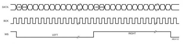
Perhaps I am missing something obvious, but in your v2.1 schematic you are providing a new WS and BCK, but you are doing nothing to synchronize with the data. If the converter does not know where either LSB or MSB are, how are you guaranteeing conversion of the appropriate word level?
-Chris
Perhaps I am missing something obvious, but in your v2.1 schematic you are providing a new WS and BCK, but you are doing nothing to synchronize with the data. If the converter does not know where either LSB or MSB are, how are you guaranteeing conversion of the appropriate word level?
-Chris
Attachments
guido said:Hi,
This looks a bit like some other stuff here. There was a post on a cambridge cd3 with 4 tda's in parallel. 4 fs filter before them and each dac got different data like this (i THINK, not shure!):
dac1 data current sample
dac2 data previous sample
dac3 data two samples back
dac4 data three samples back.
Done with 166 shift registers. The current outputs are connected together. So each datasample is 'used' four times in the output signal at different times. Claimed to be a 16x oversampling player.
Would this beneficial? I could modify a DAC, i'm working on, quite easily to do the same with two DAC's (it has no dig filter).
So 2x oversampling in total. Maybe i'll test it (GAL reprogramming).
If the above has nothing to do with the discussion here, i appologise!
Greetings,
What you describe is seems like linear interpolation, where you basically draw a line between two points and plonk down a sample halfway between. This may be alright for some signals but it would probably make a mess of audio signals. That is probably why this kind of interpolation, when used in audio, is usually preceded by more audio friendly interpolation where the new samples are a weighted average of many samples the idea being that by the time you apply linear interpolation you have enough samples to make the path formed between the interpolated signals much closer to being a straight line. This would appear to be the case with the Wadia and Cambridge dacs.
Do bear in mind, GuidoB, I could be completely wrong.

ray
hey guys, first of all thanks for the very kind words. You are more than generous I enjoy these forums as both a place to learn and to teach, I hope I can give back as much as I get Pleasure to be here ...
Now to maybe address a few questions, then on with saga !
Petter - holy smoke, some of you guys will do ANYTHING to avoid a digital interpolator !!! Just kidding ... actually, it's a clever idea you have there (or whoever first came up with it). Do you know you're actually building an FIR filter ... part digital, part analog? The digital part is of course the delay line, while the ultimate summation is the current-output summation of the DACs... pretty cool stuff Anyway, I will have to ponder the situation a bit more to give you a more specific answer, but for now, a little math :
The z-transform of a delay block is z^-1, and the resulting output of an FIR filter is simply represented by the polynomial :
OUTPUT = a + bz^-1 + cz^-2 + dz^-3 + ...
where a, b, c, d, ... are the "coefficients" that you're looking for. I think the easiest way to approach your problem is to figure out where the "zeros" of this polynomial are We want the zeros placed in the z-plane where they will be most effective ... the frequency response of your FIR filter is nothing more than the evaluation of the polynomial in the z-plane on the unit circle .... hmmmm, I'm sure I won't do justice to this in a single post
BUT ... let me say this. A coefficient set of a=1, b=2, c=1 is probably NOT a great choice, because in this case the polynomial would factor as follows :
OUTPUT = 1 + 2z^-1 + z^-2 = (1+z^-1)(1+z^-1)
which means we would have two zeros, each one at z= -1 .
Turns out that this location corresponds to half the sample rate. But it's probably not the most "efficient" use of zeros, to have both of them "piled up" at the same point on the unit circle.
More on this later ... please don't let me forget, cool ???
I enjoy these forums as both a place to learn and to teach, I hope I can give back as much as I get Pleasure to be here ...Now to maybe address a few questions, then on with saga !
Petter - holy smoke, some of you guys will do ANYTHING to avoid a digital interpolator !!!
Just kidding ... actually, it's a clever idea you have there (or whoever first came up with it). Do you know you're actually building an FIR filter ... part digital, part analog? The digital part is of course the delay line, while the ultimate summation is the current-output summation of the DACs... pretty cool stuff Anyway, I will have to ponder the situation a bit more to give you a more specific answer, but for now, a little math :The z-transform of a delay block is z^-1, and the resulting output of an FIR filter is simply represented by the polynomial :
OUTPUT = a + bz^-1 + cz^-2 + dz^-3 + ...
where a, b, c, d, ... are the "coefficients" that you're looking for. I think the easiest way to approach your problem is to figure out where the "zeros" of this polynomial are
We want the zeros placed in the z-plane where they will be most effective ... the frequency response of your FIR filter is nothing more than the evaluation of the polynomial in the z-plane on the unit circle .... hmmmm, I'm sure I won't do justice to this in a single post BUT ... let me say this. A coefficient set of a=1, b=2, c=1 is probably NOT a great choice, because in this case the polynomial would factor as follows :
OUTPUT = 1 + 2z^-1 + z^-2 = (1+z^-1)(1+z^-1)
which means we would have two zeros, each one at z= -1 .
Turns out that this location corresponds to half the sample rate. But it's probably not the most "efficient" use of zeros, to have both of them "piled up" at the same point on the unit circle.
More on this later ... please don't let me forget, cool ???
Alright, time to return to the topic at hand ... the continuing saga of Asynchronous Sample Rate Conversion !
Here's my plan : I will complete the conceptual model in this post (if it kills me), and save the corresponding mathematics for the next post.
We have concluded that what we need to do is :
1. Interpolate the data arriving at the Fs_in rate to a much higher rate, let's call it N*Fs_in ... so we are interpolating by the integer N. What this means in the time domain is simply that we need to "fill in" (N-1) audio samples in between all the original samples. We do this in two conceptual steps : first, we imagine putting (N-1) zeros in-between all the original samples, in a step cleverly called "zero-stuffing" Then, we apply the zero-stuffed sequence to an interpolation filter ... which is nothing more than a digital low-pass filter, approximating the ideal LPF.
It is very informative to describe what happens in the frequency domain when we do this step of interpolation, or "filling in" of audio samples. In the frequency domain, the original signal at the rate of Fs_in contains the baseband audio signal, faithfully represented PLUS exact duplicates or "images" centered around Fs_in (44.1kHz in our case), 2*Fs_in (88.2kHz), 3*Fs_in, etc. In fact, the original signal has frequency domain images centered around ALL integer multiples of Fs_in. This is the very nature of a discrete-time, or digital, signal in the frequency domain.
What does interpolation do? Very simple ... it simply knocks out some of those images If we had an IDEAL LPF interpolator at our disposal, the first surviving image would be at N*Fs_in, instead of Fs_in. Of course our interpolator is not perfect, it has some finite stopband rejection, so the images are not completely eliminated, only severely attenuated.
2. After we have successfully interpolated our signal by N ... or, if you prefer, "upsampled" by N we supply the most recently interpolated output when an Fs_out clock edge comes along demanding an output. No, it won't be the EXACT right output corresponding to that exact point in time ... but we are comforted in the knowledge that if N is BIG enough, we can get the error as small as we want. This is the essence of Asynchronous Sample Rate Conversion.
What we need is a "model" or description, in signal processing parlance, that describes step #2. We know all about step #1, it's nothing more than classical integer interpolation, by the integer N. But what's this "grabbing the most recent sample" business ??
Well I'm glad you asked After we interpolate by N, we've got alot more samples (in fact N times as many) ... but they still only "exist", or are only "valid", at very discrete points in time. But imagine if you will a process where, after we interpolate by N, we "hold" each value, in time, until the next sample comes along.
This "holding until the next value" will conceptually "fill in" all remaining gaps in the time domain ... so that we have essentially created a continuous-time signal. It will certainly have a bit of a "staircase" characteristic ... but the "riser" and "tread" of the stairs will be smaller for increasing values of N. And once we have created, at least conceptually, a continuous-time signal from our interpolated sequence by "holding" the last sample, we can now come along and decimate or re-sample at Fs_out ... even though it is COMPLETELY asychronous ... and achieve what I have described as "grabbing the most recent sample"
In the signal processing world, this step of "holding" is described by a classic block known (quite cleverly) as a "zero-order hold" function. It has an impulse response which is a simple boxcar or gate ... because it's job is to hold until the next sample & then forget the last one. And it's got a classic "sinx/x" frequency response ... but we'll get to the math next post.
Let's summarize our conceptual model, because we NOW have all the pieces we need : (we're adding a new step to the 2 steps above, to give a more complete signal processing picture)
1. Interpolate the input sequence, arriving at Fs_in, by the integer N to a new rate of N*Fs_in.
2. Apply a "zero-order hold" function to the interpolated sequence, filling in all points in time with the "most recently interpolated" value.
3. Decimate or sample this signal at Fs_out.
That's all there is to it. The only question is how big must N be ?
Now, one final point. For those who have stuck with me this whole thread, I mentioned very early that one way to solve this whole problem would be to just convert the original signal to analog, then re-sample at the output rate. But that would involve messy analog electronics ....
SURPRISE !!! Guess what? We have shown that "grabbing the most recently interpolated sample" is equivalent to applying a zero-order hold function to the interpolated sequence ... in other words, the Asynchronous Sample Rate Converter in fact DOES convert the signal to analog ... but it does it's job COMPLETELY in the digital domain !!!!!! Very cool indeed
Time for questions ! Next up, the math behind "finding N". Then we'll describe how we build this wonderful signal processing tool, and examine it's sensitivity to jitter.
Here's my plan : I will complete the conceptual model in this post (if it kills me), and save the corresponding mathematics for the next post.
We have concluded that what we need to do is :
1. Interpolate the data arriving at the Fs_in rate to a much higher rate, let's call it N*Fs_in ... so we are interpolating by the integer N. What this means in the time domain is simply that we need to "fill in" (N-1) audio samples in between all the original samples. We do this in two conceptual steps : first, we imagine putting (N-1) zeros in-between all the original samples, in a step cleverly called "zero-stuffing"
Then, we apply the zero-stuffed sequence to an interpolation filter ... which is nothing more than a digital low-pass filter, approximating the ideal LPF.It is very informative to describe what happens in the frequency domain when we do this step of interpolation, or "filling in" of audio samples. In the frequency domain, the original signal at the rate of Fs_in contains the baseband audio signal, faithfully represented
PLUS exact duplicates or "images" centered around Fs_in (44.1kHz in our case), 2*Fs_in (88.2kHz), 3*Fs_in, etc. In fact, the original signal has frequency domain images centered around ALL integer multiples of Fs_in. This is the very nature of a discrete-time, or digital, signal in the frequency domain.What does interpolation do? Very simple ... it simply knocks out some of those images
If we had an IDEAL LPF interpolator at our disposal, the first surviving image would be at N*Fs_in, instead of Fs_in. Of course our interpolator is not perfect, it has some finite stopband rejection, so the images are not completely eliminated, only severely attenuated.2. After we have successfully interpolated our signal by N ... or, if you prefer, "upsampled" by N
we supply the most recently interpolated output when an Fs_out clock edge comes along demanding an output. No, it won't be the EXACT right output corresponding to that exact point in time ... but we are comforted in the knowledge that if N is BIG enough, we can get the error as small as we want. This is the essence of Asynchronous Sample Rate Conversion.What we need is a "model" or description, in signal processing parlance, that describes step #2. We know all about step #1, it's nothing more than classical integer interpolation, by the integer N. But what's this "grabbing the most recent sample" business ??
Well I'm glad you asked
After we interpolate by N, we've got alot more samples (in fact N times as many) ... but they still only "exist", or are only "valid", at very discrete points in time. But imagine if you will a process where, after we interpolate by N, we "hold" each value, in time, until the next sample comes along.This "holding until the next value" will conceptually "fill in" all remaining gaps in the time domain ... so that we have essentially created a continuous-time signal. It will certainly have a bit of a "staircase" characteristic ... but the "riser" and "tread" of the stairs will be smaller for increasing values of N. And once we have created, at least conceptually, a continuous-time signal from our interpolated sequence by "holding" the last sample, we can now come along and decimate or re-sample at Fs_out ... even though it is COMPLETELY asychronous ... and achieve what I have described as "grabbing the most recent sample"
In the signal processing world, this step of "holding" is described by a classic block known (quite cleverly) as a "zero-order hold" function. It has an impulse response which is a simple boxcar or gate ... because it's job is to hold until the next sample & then forget the last one. And it's got a classic "sinx/x" frequency response ... but we'll get to the math next post.
Let's summarize our conceptual model, because we NOW have all the pieces we need : (we're adding a new step to the 2 steps above, to give a more complete signal processing picture)
1. Interpolate the input sequence, arriving at Fs_in, by the integer N to a new rate of N*Fs_in.
2. Apply a "zero-order hold" function to the interpolated sequence, filling in all points in time with the "most recently interpolated" value.
3. Decimate or sample this signal at Fs_out.
That's all there is to it. The only question is how big must N be ?
Now, one final point. For those who have stuck with me this whole thread, I mentioned very early that one way to solve this whole problem would be to just convert the original signal to analog, then re-sample at the output rate. But that would involve messy analog electronics ....
SURPRISE !!! Guess what? We have shown that "grabbing the most recently interpolated sample" is equivalent to applying a zero-order hold function to the interpolated sequence ... in other words, the Asynchronous Sample Rate Converter in fact DOES convert the signal to analog ... but it does it's job COMPLETELY in the digital domain !!!!!! Very cool indeed
Time for questions ! Next up, the math behind "finding N". Then we'll describe how we build this wonderful signal processing tool, and examine it's sensitivity to jitter.
Petter said:
If I time-shift each of the n units ... and add the outputs together, I end up with a low pass filtered result of sorts by nature of averaging and moving spectrum higher.
The spectrum is not moved up, but rather you introduce a comb filter with a bunch of zeroes at specific intervalt. See Werewolf's earlier reply.
Indeed, your delayed-added DAC outputs constitute a very simple, unsophisticated FIR lowpass filter, with coefficients you've gotten to not by signal theory and filter synthesis, but rather by whatever is feasible given the amount of DACs etc. you have available. So in short, it is a rather naive approach to low-pass filtering.
This was done in the Cambridge CD2 and CD3 CD-players, both of them boasting '16 x oversampling' from 4 TDA1541s.
Even earlier something similar was done in the Philips 104-based Mission DAD7000 CD-player, with one TDA1540 and presumably an analogue delay of half the sample period.
But let me now strongly suggest to let Werewolf carry on with his actual lecture on ASRC, and ask the questions afterwards. Otherwise we run the risk of this thread diluting a bit prematurely.
1. Interpolate the data arriving at the Fs_in rate to a much higher rate, let's call it N*Fs_in ... so we are interpolating by the integer N. What this means in the time domain is simply that we need to "fill in" (N-1) audio samples in between all the original samples. We do this in two conceptual steps : first, we imagine putting (N-1) zeros in-between all the original samples, in a step cleverly called "zero-stuffing" Then, we apply the zero-stuffed sequence to an interpolation filter ... which is nothing more than a digital low-pass filter, approximating the ideal LPF.
I said this in an earlier post, but was told it would not work - I appreciate I had little time to write the post so it was not very clear, but my answer could have been expanded upon.
As to your method of sample rate conversion, I would guess that upsampling to the rate of 2,116,800,000 (the product of 44.1KHz and 48KHz) then using a very high quality FIR (as I stated originaly) then downconverting (averaging samples) would, theoretically, be the best way to do things. Although not a practical solution as the conputation and mere clock speeds are huge, would this not be the ideal way to do things in theory?
Also with regards to reclocking, could one not use some form of memory that has asynchronous read/write capability and store the samples using the original clock (recovered by PLL or similar) and send them to the DAC using a new clock source with much better jitter performance?
annex - your idea of interpolating to a rate equal to 44.1kHz*48kHz, and then decimating down to 48kHz is a very good one ... in a SYNCHRONOUS environment. In fact, you wouldn't need to go that far to satisfy integer interpolation/decimation ... you only need to interpolate the 44.1kHz by the integer 160, to a rate of 7.056MHz ... which you could then decimate by 147 to a rate of 48kHz.
But this would only work in a SYNCHRONOUS environment, where the two clocks are derived from the SAME master ... which would mean that there is a fundamental time base I can use to measure EXACTLY 44.1kHz, and EXACTLY 48kHz.
Couple ways to think about the problem:
1. Input data arrives at 44.1kHz, which we have called Fs_in. Let's say I have any multiple of this particular clock available to me, so I choose to interpolate this input by exactly 160. So now I have input data that corresponds to an input sample rate of 7.056MHz. All I need to do is take every 147th sample, and I have my samples at Fs_out, right ? Unfortunately, no Because the samples I generate when I decimate by 147, although they look like 48kHz when measured against Fs_in, will NOT line up with Fs_out !!! The "two" 48kHz rates can never be identical, because they are generated from two fundamentally different clocks.
2. Another way to consider the problem. Assume there is a master, universal timepiece somewhere, against which I can measure ALL clocks (of course Einstein has shown that such a thing, like the ether, does not & need not exist ... but that would surely be a topic for another thread!). So maybe my input rate Fs_in is, in fact, PRECISELY 44.1kHz. But my Fs_out rate is 48.01kHz, instead of 48kHz. And in another system that wants to use the SAME sample rate converter, the Fs_out rate is 47.93 kHz.
I need a device that's flexible enough to handle ALL these situations. Now you may think, "well, they are all pretty close to 48kHz, what's the big deal?" Turns out it is a VERY big deal ... imagine drawing 2 timelines, one with 48kHz "ticks" and one with 47.93kHz "ticks". Even if they START at the exact same tick, they will DIVERGE in their time alignment pretty quickly. So the audio samples that correctly correspond to the first timeline will, pretty quicly, start to look NOTHING like the samples that correctly correspond to the second timeline.
Does that make sense?
We really have NO choice but to create a continuous-time signal from which we can decimate ... because clock alignment can NEVER happen in an asynchronous environment, no matter how far we interpolate. That's a VERY, VERY important point
But I do have a couple CHOICES for how I create a continuous-time signal :
Choice 1 : Use a DAC followed by an ADC .... yuck it's not all-digital.
Choice 2 : Interpolate the data by a big enough number N, then apply ... CONCEPTUALLY ... a zero-order hold function. This EFFECTIVELY creates a continuous time, or analog, signal. In practise, my digital ASRC will never really apply the zero-order hold function ... it will just grab the most recently interpolated sample when an Fs_out clock edge comes along. But these two operations are mathematically IDENTICAL.
We will also see that this technique, and the math required to estimate how big N must be, is absolutely INDEPENDENT of the Fs_out rate ... meaning that the exact same hardware can be used to support a WIDE variety of asynchronous output rates ... with one provision : Fs_out must be greater than Fs_in. Actually, this is not a fundamental limitation, and available hardware chips (CS8420, AD1896) do NOT have this limitation ... the picture (and hardware) just gets a bit more complicated when Fs_out is less than Fs_in. We may get to it, if this thread doesn't die from excessive length first !
But this would only work in a SYNCHRONOUS environment, where the two clocks are derived from the SAME master ... which would mean that there is a fundamental time base I can use to measure EXACTLY 44.1kHz, and EXACTLY 48kHz.
Couple ways to think about the problem:
1. Input data arrives at 44.1kHz, which we have called Fs_in. Let's say I have any multiple of this particular clock available to me, so I choose to interpolate this input by exactly 160. So now I have input data that corresponds to an input sample rate of 7.056MHz. All I need to do is take every 147th sample, and I have my samples at Fs_out, right ? Unfortunately, no
Because the samples I generate when I decimate by 147, although they look like 48kHz when measured against Fs_in, will NOT line up with Fs_out !!! The "two" 48kHz rates can never be identical, because they are generated from two fundamentally different clocks.2. Another way to consider the problem. Assume there is a master, universal timepiece somewhere, against which I can measure ALL clocks (of course Einstein has shown that such a thing, like the ether, does not & need not exist ... but that would surely be a topic for another thread!). So maybe my input rate Fs_in is, in fact, PRECISELY 44.1kHz. But my Fs_out rate is 48.01kHz, instead of 48kHz. And in another system that wants to use the SAME sample rate converter, the Fs_out rate is 47.93 kHz.
I need a device that's flexible enough to handle ALL these situations. Now you may think, "well, they are all pretty close to 48kHz, what's the big deal?" Turns out it is a VERY big deal ... imagine drawing 2 timelines, one with 48kHz "ticks" and one with 47.93kHz "ticks". Even if they START at the exact same tick, they will DIVERGE in their time alignment pretty quickly. So the audio samples that correctly correspond to the first timeline will, pretty quicly, start to look NOTHING like the samples that correctly correspond to the second timeline.
Does that make sense?
We really have NO choice but to create a continuous-time signal from which we can decimate ... because clock alignment can NEVER happen in an asynchronous environment, no matter how far we interpolate. That's a VERY, VERY important point
But I do have a couple CHOICES for how I create a continuous-time signal :
Choice 1 : Use a DAC followed by an ADC .... yuck
it's not all-digital.Choice 2 : Interpolate the data by a big enough number N, then apply ... CONCEPTUALLY ... a zero-order hold function. This EFFECTIVELY creates a continuous time, or analog, signal. In practise, my digital ASRC will never really apply the zero-order hold function ... it will just grab the most recently interpolated sample when an Fs_out clock edge comes along. But these two operations are mathematically IDENTICAL.
We will also see that this technique, and the math required to estimate how big N must be, is absolutely INDEPENDENT of the Fs_out rate ... meaning that the exact same hardware can be used to support a WIDE variety of asynchronous output rates ... with one provision : Fs_out must be greater than Fs_in. Actually, this is not a fundamental limitation, and available hardware chips (CS8420, AD1896) do NOT have this limitation ... the picture (and hardware) just gets a bit more complicated when Fs_out is less than Fs_in. We may get to it, if this thread doesn't die from excessive length first !
werewolf said:Choice 1 : Use a DAC followed by an ADC .... yuck
Positively excellent tutorial - and many thanks! However, concerning the above statement: So, just what's *wrong* with analog???!!!
I seem to recall having a conversation many years ago in school when we argued about whether the universe was actually analog or digital (but with infinite resolution) I believe that one of those that *insisted* on the analog view was Dave Welland - (but that was after many beers) So there!Just a slightly humorous aside - now please continue with our regularly scheduled program - very informative!
How big must N be ?
In other words, how far must we interpolate the data arriving at Fs_in, so that the error created by grabbing the most recently interpolated sample at Fs_out is acceptably low?
Mathematically, this operation is described by applying a zero-order hold function on the interpolated data, followed by asychronous decimation to Fs_out. In the time domain, this holding operation completely "fills in" the small remaining gaps between the interpolated data points ... effectively creating an analog signal
In the frequency domain, the zero-order hold applies the following filter function to the interpolated data :
ZOH = sin[pi*f/(N*Fs_in)]/[pi*f/(N*Fs_in)] = form of "sinx/x"
where f = frequency, and N*Fs_in = interpolated sample rate.
This ZOH function is serving to attenuate the images that REMAIN after interpolation by N ... ultimately approximating an analog signal. So, the most troublesome image will be at a frequency given by :
f = N*Fs_in - 0.5*Fs_in
Now all we need to do, is use this value for "f" in our ZOH expression, and figure out what "N" needs to be for a given spec we're trying to hit. What's the spec? Well, remember that all remaining images ... these include TWO categories : residual image energy from the stopband of the interpolate-by-N filter, PLUS residual image energy from the ZOH function ... will ultimately find their way to the audioband when we decimate by Fs_out. So, we need a VERY GOOD spec for the ZOH function, let's say somewhat consistent with 24-bit audio processing. SO let's pick -120dB
Well, you guys can check the math and find the following :
Residual ZOH images = -120dB requires N=2^19 !!!
Residual ZOH images = -126dB requires N=2^20 !!!
The AD1896 operates with N = 2^20 ~ 1 MILLION. Yes, I typed that correctly ... the effective interpolated output rate in the AD1896 is 44.1kHz*(2^20) = 46 Gigahertz !! And that's just for a 44.1kHz input rate ....
But this is how far you must "effectively" interpolate, so that the "error" from grabbing the most recently interpolated sample upon asynchronous decimation, will be on the order of -126dB.
How in the world does one build a cost effective interpolator to upsample to 50 GHz ... and beyond (for higher input rates) ???
That's the discussion for the next post
But first, let's keep something in perspective. Our interpolation operation on the Fs_in data MUST be ultra clean, because ALL of the residual image energy will ALIAS back down into the audio band when we decimate down to Fs_out. This is NOT the same case for residual image energy out of DACs, for example ... the residual high frequency images coming out of DACs will only trouble the audio band through soft nonlinearities, and the accompanying intermodulation, in the analog stages that FOLLOW the DAC ... a much less severe problem than asychronous decimation.
In summary ... remember when I said that the interpolator's stopband was NOT the ONLY thing to worry about in Asynchronous Sample Rate Conversion? Now we know why ... there are TWO stopband non-idealities to consider :
1. Stopband rejection of the interpoalte-by-N low-pass filter.
2. Residual images resulting from our Zero-Order Hold.
In this post we found that , in order to keep the second component down around -126dB, N must be astronomically huge ... on the order of 2^20.
In other words, how far must we interpolate the data arriving at Fs_in, so that the error created by grabbing the most recently interpolated sample at Fs_out is acceptably low?
Mathematically, this operation is described by applying a zero-order hold function on the interpolated data, followed by asychronous decimation to Fs_out. In the time domain, this holding operation completely "fills in" the small remaining gaps between the interpolated data points ... effectively creating an analog signal
In the frequency domain, the zero-order hold applies the following filter function to the interpolated data :
ZOH = sin[pi*f/(N*Fs_in)]/[pi*f/(N*Fs_in)] = form of "sinx/x"
where f = frequency, and N*Fs_in = interpolated sample rate.
This ZOH function is serving to attenuate the images that REMAIN after interpolation by N ... ultimately approximating an analog signal. So, the most troublesome image will be at a frequency given by :
f = N*Fs_in - 0.5*Fs_in
Now all we need to do, is use this value for "f" in our ZOH expression, and figure out what "N" needs to be for a given spec we're trying to hit. What's the spec? Well, remember that all remaining images ... these include TWO categories : residual image energy from the stopband of the interpolate-by-N filter, PLUS residual image energy from the ZOH function ... will ultimately find their way to the audioband when we decimate by Fs_out. So, we need a VERY GOOD spec for the ZOH function, let's say somewhat consistent with 24-bit audio processing. SO let's pick -120dB
Well, you guys can check the math
and find the following :Residual ZOH images = -120dB requires N=2^19 !!!
Residual ZOH images = -126dB requires N=2^20 !!!
The AD1896 operates with N = 2^20 ~ 1 MILLION. Yes, I typed that correctly ... the effective interpolated output rate in the AD1896 is 44.1kHz*(2^20) = 46 Gigahertz !! And that's just for a 44.1kHz input rate ....
But this is how far you must "effectively" interpolate, so that the "error" from grabbing the most recently interpolated sample upon asynchronous decimation, will be on the order of -126dB.
How in the world does one build a cost effective interpolator to upsample to 50 GHz ... and beyond (for higher input rates) ???
That's the discussion for the next post
But first, let's keep something in perspective. Our interpolation operation on the Fs_in data MUST be ultra clean, because ALL of the residual image energy will ALIAS back down into the audio band when we decimate down to Fs_out. This is NOT the same case for residual image energy out of DACs, for example ... the residual high frequency images coming out of DACs will only trouble the audio band through soft nonlinearities, and the accompanying intermodulation, in the analog stages that FOLLOW the DAC ... a much less severe problem than asychronous decimation.
In summary ... remember when I said that the interpolator's stopband was NOT the ONLY thing to worry about in Asynchronous Sample Rate Conversion? Now we know why ... there are TWO stopband non-idealities to consider :
1. Stopband rejection of the interpoalte-by-N low-pass filter.
2. Residual images resulting from our Zero-Order Hold.
In this post we found that , in order to keep the second component down around -126dB, N must be astronomically huge ... on the order of 2^20.
- Status
- This old topic is closed. If you want to reopen this topic, contact a moderator using the "Report Post" button.
- Home
- Source & Line
- Digital Source
- Asynchronous Sample Rate Conversion