Hi
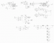
Any opinions or improvements suggestions about this WM8741 dac circuit ?
The WM8741 section of that circuit are quite different than the circuit suggested by Wolfson.
I don't know why there is a 74HC157 in that circuit, it's look like a reclock.
Is there any errors in that WM8741 dac circuit ?
I include the image of that circuit.
Thanx
Paul
Attachments
Last edited:
I would either omit R6 and R9 altogether, or replace them with active current-sources. The reason being is that those resistors may significantly load down the output stage of the op-amps, especially so for R6. While simple resistors will produce the D.C. bias offset needed to ensure class-A operation of the output stage, they then also produce an unnecessarily low A.C. loading of the output. The significantly increased A.C. loading works counter to the distortion improvement gained by the class-A D.C. biasing.
Run your RC networks at much higher (more than 10X higher) impedances to reduce opamp loading. I've found this pays considerable dividends in terms of perceived dynamics.
With higher impedances you'll need less 'classA' biassing, the resistors as Ken points out are rather loading down the outputs.
With higher impedances you'll need less 'classA' biassing, the resistors as Ken points out are rather loading down the outputs.
I concur with abraxalito's observation. While most op-amp data sheets and many engineers are looking to minimze noise by minimizing the surrounding network impedances, I feel that the affect of such loading is sonically not worth the reduction in noise. In short, I find distortion more annoying than uncorrelated noise.
One advantage I've found of running very high network impedances is I can use TL084s as the opamps without any apparent penalty in sound quality.
A recent example - the active speakers I'm playing with have a 'Linkwitz transform' kind of input circuit. In these its a 6dB peaking Sallen-Key high pass filter set with the peak about 75Hz. The original cap values are 100nF. I have found improvement in dynamics (particularly in the bass) from taking those caps all the way down to 2nF and raising the resistor values 50-fold. In the past I'd have not considered such high resistor values (it needs 4M at the opamp input) due to noise worries. Naturally enough this probably couldn't be practically realized with bipolar input opamps.
A recent example - the active speakers I'm playing with have a 'Linkwitz transform' kind of input circuit. In these its a 6dB peaking Sallen-Key high pass filter set with the peak about 75Hz. The original cap values are 100nF. I have found improvement in dynamics (particularly in the bass) from taking those caps all the way down to 2nF and raising the resistor values 50-fold. In the past I'd have not considered such high resistor values (it needs 4M at the opamp input) due to noise worries. Naturally enough this probably couldn't be practically realized with bipolar input opamps.
- Status
- This old topic is closed. If you want to reopen this topic, contact a moderator using the "Report Post" button.
- Home
- Source & Line
- Digital Source
- Questions about a WM8741 dac circuit