I'm not sure what would be the usefullness of recentering to 2.5V. Wouldn't it be easier to simply put a smal opamp in between the microcontroller and the input with a gain of 2? That would allow you to use the ADC full potential in terms of precision (usually around 10 to 13 bits)
I'm not entirely sure my answer will be of any use, but at least I tried")
Sébastien
I'm not entirely sure my answer will be of any use, but at least I tried
Sébastien
Hello
I'm not have experience like this but I will try.
Please thinking to pushpull amplifier that seperate signal sine wave to 2 signal by diode, first channel signal for positive and second one for negative signal. After that we change negative signal on second one to positive by opamp(changing phase).
Right now we have two signal both is positive and we will use 2
channel of ADC to check level of signal and if signal come from first channel that mean positive signal and if signal come from
second channel that mean negative signal. After that up to your programming to go ahead.
If possible don't forget to let me know.
Don't forget that your MC (probably) can't produce any _high_ fidelity of the audio signal.martinfuture said:I'm building a PWM amplifier using a microcontroller and I want to use the microcontroller's internal ADC. However it only accepts input voltages 0-5V. How can I recenter an audio signal to ~2.5V?
You may find that simply biasing the ADC input to half-supply using a couple of resistors, and then ac coupling the signal in will be adequate. (That is, if you don't need a response down to 0Hz of course.)
If you need a response down to 0Hz, then you'll have to use op-amp circuitry to offset the signal midpoint to VCC/2.
If you need a response down to 0Hz, then you'll have to use op-amp circuitry to offset the signal midpoint to VCC/2.
i hate to say that it's almost always a good idea to buffer the input of an ADC anyway --- if it's a PIC or AVR the datasheet will tell you the approximate impedance. Some of the switched capacitor ADC's have pretty low impedance. some of theses microcontrollers can be very unforgiving of higher than specified voltages.
You could spend a couple hours trying to figure out a biasing scheme with discretes, but an op amp is so easy to implement.
in order not to "fry" the ADC input of the microcontroller consider connecting a clamping diode (1n4148) to the input of the ADC, a small resistor in series with the ADC input will also isolate some of the noise picked up on the trace -- i picked up this idea in the datasheet from the Linear Tech LT1093 6-input/10 bit ADC and it definitely works.
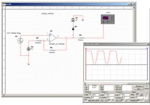
The picture below will give you some idea of what I am driving toward. It shows the 2.5 VAC signal to the ADC biased and "clipped" by the diode.
You could spend a couple hours trying to figure out a biasing scheme with discretes, but an op amp is so easy to implement.
in order not to "fry" the ADC input of the microcontroller consider connecting a clamping diode (1n4148) to the input of the ADC, a small resistor in series with the ADC input will also isolate some of the noise picked up on the trace -- i picked up this idea in the datasheet from the Linear Tech LT1093 6-input/10 bit ADC and it definitely works.
The picture below will give you some idea of what I am driving toward. It shows the 2.5 VAC signal to the ADC biased and "clipped" by the diode.
Attachments
With CMOS micros it's wise to clamp both over and under-voltages to the ADC input. On the HC908 range for example, the ADC inputs are high-impedance but have a max capacitance of 30pf.
A 1k series resistor in line with the signal to the ADC, together with a couple of low-power Schottky signal diodes (one with the cathode connected to Vdd and the anode to the ADC input pin, the other diode with the anode connected to 0v and the cathode to the ADC input pin) will protect the chip against most things.
What is the micro? Most only have 12-bit ADCs at best, and they are only fairly slow successive approximation types. Are you sure the speed and resolution will be adequate?
- Status
- This old topic is closed. If you want to reopen this topic, contact a moderator using the "Report Post" button.
- Home
- Source & Line
- Digital Source
- Microcontroller input question