Hello everyone!
I write here because I hope to get some information or advice of any kind on the use of shunt regulators to implement the power of a CD player STUDER A727.
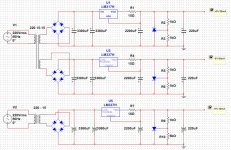
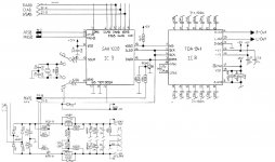
One of the changes I made consists in a dedicated power supply for the TDA1541 based on the LM317 / 337 used as current sources followed by TL431.
The schematics is published below.
The result was immediately positive, although there are still some things that i need to understand better.
The main feature of this type of PSU than with the LM317 / 337 was, (in my case), greater fluidity and transparency of the medium and high frequencies.
Instead, what I don't like so much are the bass frequencies that seems to have lost a little bit of "speed and presence".
Doing various tests I realized that the capacitors placed between the TL431 and the TDA1541 have a very significant influence on the final result, so i think that it is possible that finding the right kind and value of capacity, the question of the bass will be resolved.
Looking on the web, I have seen that there is no fixed rule for the value of the capacity (if not to prevent the auto-oscillation of the TL431).
Many projects have values like 10uF, others 220uF, others 470uF ...
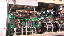
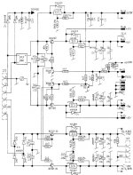
I Place below the images of the schematics that I used and the fotos of the work completed.
There is someone who has already experienced with this kind of power supplies?
ANY COUNCIL, RECOMMENDATION OR SUGGESTION IS VERY WELL ACCEPTED.
Ciao!
I write here because I hope to get some information or advice of any kind on the use of shunt regulators to implement the power of a CD player STUDER A727.
One of the changes I made consists in a dedicated power supply for the TDA1541 based on the LM317 / 337 used as current sources followed by TL431.
The schematics is published below.
The result was immediately positive, although there are still some things that i need to understand better.
The main feature of this type of PSU than with the LM317 / 337 was, (in my case), greater fluidity and transparency of the medium and high frequencies.
Instead, what I don't like so much are the bass frequencies that seems to have lost a little bit of "speed and presence".
Doing various tests I realized that the capacitors placed between the TL431 and the TDA1541 have a very significant influence on the final result, so i think that it is possible that finding the right kind and value of capacity, the question of the bass will be resolved.
Looking on the web, I have seen that there is no fixed rule for the value of the capacity (if not to prevent the auto-oscillation of the TL431).
Many projects have values like 10uF, others 220uF, others 470uF ...
I Place below the images of the schematics that I used and the fotos of the work completed.
There is someone who has already experienced with this kind of power supplies?
ANY COUNCIL, RECOMMENDATION OR SUGGESTION IS VERY WELL ACCEPTED.
Ciao!
Attachments
You should have a look on the Blog section at the PS of Nazaar member.
Despite the 220 uF help maybe to lower the impedance at highest frequency, it's also certainly a brake to dynamic and transcient...
Did you try to bypass with 0.2 uF smd caps near the load (pin 15,28,27) ? And remove the 220 uF cap ! I will try this first !
You could also add a resistor between the two main first cap for a Pi filtering.
Have a local filtering for the tl431, and use it too feed a discrete darlington (or at least an already made like TIP142/147) for an emitter follower.
But sorry, no precise shematic in mind, just a testimonial from personal experience with this chip !
Last edited:
I have experience with LM317T into TL431 power supplies. They do have a tendency to oscillate (the LM317 does). The solution I have found to work is putting a damped inductor (33uH I used, in parallel with 200ohms) in series with the LM317.
Note you don't need to use LM337 - its even more unstable than LM317 - just turn the LM317 through 180degrees.
Note you don't need to use LM337 - its even more unstable than LM317 - just turn the LM317 through 180degrees.
Hello. Thank you all for the interesting hints. ")
Another thing that i forgot to say is that the voltages for +/-5 volt for the truth are +/-4.97 volts.
I think that the difference between 4.97 and 5 should be nothing... but is true? How does it matter?
About an eventually auto oscillating of the LM, how can i measure it? I imagine that a oscilloscope is needed.
I measured those values with a multimeter during play music but they appear to be very stable and nothing change...
And about putting a damped inductor (33uH in parallel with 200ohms) in series with the LM317, where I have to put it? Before or after it?
Thank you again for the hints!
An oscilloscope is the only way to confirm its oscillating yes - but there are symptoms that might be evident from measuring with a multimeter. Such as there not being 1.25V across the current setting resistor (15ohms in your schematic). If your voltages stabilize quickly and you get the 1.25V in the right place then maybe you've escaped oscillation.
Given that the LM317 configured as a current source is a two terminal device it matters not which side the damped inductor is placed.
Given that the LM317 configured as a current source is a two terminal device it matters not which side the damped inductor is placed.
Small difference doesn't matter for the TDA1541 ! Mine (with shunt stabilizer) beginns at 4.7 and is around 5 whent hot, most of the time at 4.9V ! My -15V is at -15.4 V !
Note I use the term stabilizer and not regulator because of this !
If your question was about tda1541 performances and exact voltage needed, you are ok, you will hear no difference in this small range, like mine above.
Note I use the term stabilizer and not regulator because of this !
If your question was about tda1541 performances and exact voltage needed, you are ok, you will hear no difference in this small range, like mine above.
Ok guys. Thanks for the valuables advices!
I did more and different test.
The TL431 seems not oscillate because the 1.25V across the current setting resistor is stabilized immediately at power on and is stable even when using the machine.
First of all I put a resistance between the first two capacitors.
Then, following your advice I started to decrease the value of the capacity decreasing from 220uF to 100uF to 47uF to 22uF to 10uF.
The amazing thing is that every decrease in the value of the capacity there has been a corresponding improvement ...
(I tried various values and various types of capacitors such as Panasonic FC, Rubycon, Nichicon, Sanyo OS ...)
Basically I got the best sound by removing all the skills ...
I then left alone bypass capacitors coming up to 330nF, trying MKT and MKP.
Compared to the initial situation, in fact there was a very tangible improvement ... but still ... there was something that did not convince me.
I eventually reconnected the original power and I must say that this is still the best ...
I know that there are a lot of more shunt power supply that are really better compared to the type that I used, especially for the first part of the circuit ... But they are not easily achievable on the pcb holes ...
Maybe it is likely that the Studer A727 has already perceived a very well done power supply... or maybe that sounds better with a power supply (maybe anyway dedicated) but with the classic LM regulators such as those already used... not really I know ... There are many variables in play...
I do not know ... I'm a bit 'confused about why still reading around on the net there is a lot of people (like you), which uses shunt power supply with excellent results ... and of this I am convinced!
I hope the night will bring good advice... then i will decide what to do!
Thanks again for all the valuable information !!!
CIAO!!!
p.s sorry if my english is not perfect!!!
Yes possible ! There is something missing in your experiment ! Please, what is your 3300 uF and 2200 uF serie/brand?
Please play with that and keep the small value at local decoupling of the caps with PPS, NPO, X7R (but here smalling size case to try something different with a better inductance) !
An equilibrium has to be found for each supply/dac layout... in relation to the rest of the whole hifi system ! Not an easy task but a personal setup to try to extract life of your DAC... and the better speaker is sounding dull without that !
As Abrax said : those regs not being so bad for a TDA1541 add problems (while not being more important than a sota supply... while a sota supply whithout the good caps is not a sota supply ! )
But I believe you have a very good margin just playing with caps imho ! Go for the advices of Abrax about supply, he knows what should be done,I can give you one tip about caps or two in relation of your needs !
Please play with that and keep the small value at local decoupling of the caps with PPS, NPO, X7R (but here smalling size case to try something different with a better inductance) !
An equilibrium has to be found for each supply/dac layout... in relation to the rest of the whole hifi system !
Not an easy task but a personal setup to try to extract life of your DAC... and the better speaker is sounding dull without that !As Abrax said : those regs not being so bad for a TDA1541 add problems (while not being more important than a sota supply... while a sota supply whithout the good caps is not a sota supply ! )
But I believe you have a very good margin just playing with caps imho ! Go for the advices of Abrax about supply, he knows what should be done,I can give you one tip about caps or two in relation of your needs !
Last edited:
Hello Heldam.
Regarding the 3300uF and 2200uF capacitors, them are Panasonic FC and from what I read on the net should be good...
I also tried changing the local decoupling by type and size, but without really interesting results...
I mean that the result is not bad ... but it does not sound as good as the original power supply...
A great truth that you said, is that the variables involved in a whole system are a lot, and often is not easy to find the right and optimal balance until after many tests.
One question come in to my mind... why many manufacturers have used LM type regulators and not shunt regulators?
Maybe the shunt regulators did not exist at the production time of "older" machines?
Or maybe the older machines and topologies go better with LM?
In effect, i see that shunt regulators are widely used in the modern DACs design... but not CD player... maybe...
Though generally the schematics are more or less the same for the 1541 also if the machine have different features.
Please can you describe me briefly the mains features of your DAC system?
Although still not able to get a very good performance from this power supply I'm convinced that there must be a good setting also for my Studer... maybe not easy to reach... but there must be...
CIAO!
Before you choose for a new shunt supply or while waiting for it (note a shunt supply has to be near the load but if it has sensing option):
Apply advices above about oscillation.
try to put a 1W or 2W resistor between the two 3300 uF while cutting the trace between them ! Value for the resistor has not to be so high it drops the voltage needed at the input of the regs for regulation (I assume LM317 should drop 2 or 3 V minimum to regulate (check!)...). Here the better is to measure (without making shorts! ) ! 2 ohms e.g to ??? ohms for the resistor !
On the second 3300 uF cap try to // with 330 to 1000 uF with Panasonic FC and FM (keep the one you prefer after listening to) !
After try to bypass the 2200 uF with 0.22 uF (PPS cap or NPO between the legs : look at datasheet to find the size case in relation to the pitch legs of the main cap - knowing than the littliest case size the better inductance : X7R with 0603 case size could be tryed as well, like radial MKT, etc...MKP is too big for that. You should also try a bypass with 220 to 1000 uF (again with FC and FM...OSCON SP, Black Gate if having it).
I surmise you have also caps on the pins of the TDA chip ? (pin 15 (-15V) ; pin 28 (5V), pin 26 (-5V) ? Blue MKT from Philips (a very specific sounding signature) or ceramic ? Which values ? You should know that before continue to tweaking, shoot some photograph to come back on initial conf, etc !)...
To answer to your question I have an Audial AYA2 and had many TDA1541/1540/1545/1543 and som others Philips DAC chips... My actual DAC is an AYA2 2014 from Audial with some personal setup and feed in simultaneous mode (not I2S) with an USB to I2S board from Lorien member (Luckit website) and soon with a reclocker and FIFO from IanCanada with reliable clock board with good phase noise from Andrea Mori member or IanCanada ones with crystals from Laptech !
AYA2 2014 from Audial uses shunts regs without TL431 to feed the dac chip with curent constant source and darlington emitter follower... I can't say more to you as it's patented and I respect that as Pedja Rogic the creator who is a nice guy.
Apply advices above about oscillation.
try to put a 1W or 2W resistor between the two 3300 uF while cutting the trace between them ! Value for the resistor has not to be so high it drops the voltage needed at the input of the regs for regulation (I assume LM317 should drop 2 or 3 V minimum to regulate (check!)...). Here the better is to measure (without making shorts! ) ! 2 ohms e.g to ??? ohms for the resistor !
On the second 3300 uF cap try to // with 330 to 1000 uF with Panasonic FC and FM (keep the one you prefer after listening to) !
After try to bypass the 2200 uF with 0.22 uF (PPS cap or NPO between the legs : look at datasheet to find the size case in relation to the pitch legs of the main cap - knowing than the littliest case size the better inductance : X7R with 0603 case size could be tryed as well, like radial MKT, etc...MKP is too big for that. You should also try a bypass with 220 to 1000 uF (again with FC and FM...OSCON SP, Black Gate if having it).
I surmise you have also caps on the pins of the TDA chip ? (pin 15 (-15V) ; pin 28 (5V), pin 26 (-5V) ? Blue MKT from Philips (a very specific sounding signature) or ceramic ? Which values ? You should know that before continue to tweaking, shoot some photograph to come back on initial conf, etc !)...
To answer to your question I have an Audial AYA2 and had many TDA1541/1540/1545/1543 and som others Philips DAC chips... My actual DAC is an AYA2 2014 from Audial with some personal setup and feed in simultaneous mode (not I2S) with an USB to I2S board from Lorien member (Luckit website) and soon with a reclocker and FIFO from IanCanada with reliable clock board with good phase noise from Andrea Mori member or IanCanada ones with crystals from Laptech !
AYA2 2014 from Audial uses shunts regs without TL431
to feed the dac chip with curent constant source and darlington emitter follower... I can't say more to you as it's patented and I respect that as Pedja Rogic the creator who is a nice guy.
Last edited:
Hello. I already put the resistors between the two 3300 uF capacitor, and obviously they are low value (15 ohm for the +/-5 and 10 for -15) so the voltage drop on those resistors are low... 1.2V and 0.6V.
Abot cap on the tda pins IN THE ORIGINAL CONFIGURATION I have two 100uF capacitor paralleled and 22nF (but white not blu... don't know if they are philips).
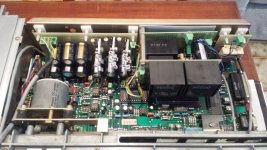
Anyway... under here there are the photo of the original configuration.
Nothing special maybe... but still wonderfull sound...
CIAO!
Abot cap on the tda pins IN THE ORIGINAL CONFIGURATION I have two 100uF capacitor paralleled and 22nF (but white not blu... don't know if they are philips).
Anyway... under here there are the photo of the original configuration.
Nothing special maybe... but still wonderfull sound...
CIAO!
Attachments
Yes the little blue MKT of the first photograph are Philips ! (very specific sound signature)
How looks the two 100 uF of the +5V pin ? little Brown ceramic smd caps or radial chemical ?
I would keep the 0.022 uF at -5 & -15V !
Are you still with the supply of post 1 or the one of the shematic above ? If yes, try to remove the 2 x 100 uF at +5V (do it carefully to keep them and going back if you need it) and swap them with 0.22 uF to 1 uF (MKT or better smd PPS or ceramic).
I asssume the 100 uf are radial chemical caps or if the one with red marking, certainly Nichicon FP serie polymer caps (near the SA7020 chip?) and the 22 nF the blue radial MKT ?
I don't like the Nichicon FP at all (dull while being soft), not sure it was a good idea to put them here ! Remove them and keep the blue mkt if you are using the shematic of the first post with my modification about bypass cap I given above (you just need to buy some caps if not having the smaller value of FM & FC but you can beginn with OSCON SP or Black Gate if you have it). At least my humble opinion and what I try first !
Always work with the same songs and albums to benchmark your revisions between each others !
Last edited:
Hello Eldam.
Some small news about the situation:
Before leaving the shunt power supply I made other test but every time failed to overcome the result of the original power supply...
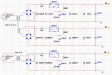
At this point I decided not to throw the job done and I modified the pcb I used to do the shunt psu and I built another psu on the basis of the original (and based on the material that I already had)
The diode bridges used for the +/- 5V are W04 while for the -15V I used BYV27 diodes.
As for capacity, the first two 3300uF capacitors are Panasonic FA, those from 2200uF after regulators are Panasonic FK, the 220uF on the -15V is Panasonic FM.
As regards the two 100uF on the + \ - 5v these are of Nichicon FP.
Every 100nF capacitor is Philips orange MKT.
For now, this seems to be the best configuration (with the material that i already have).
The amazing thing is that the small 100nF capacitor are very important for the entire result.
Off course, I'll do other test but respect than the original PSU, this go really better!!! Bass are really powerfull and fast, but the wonderfull thing is that it seems that "now the music is out of the speakers "...
So... it seems that this is the right way for my system...
Please, i'll be very happy to receive any kind of advice!
CIAO!!!
Some small news about the situation:
Before leaving the shunt power supply I made other test but every time failed to overcome the result of the original power supply...
At this point I decided not to throw the job done and I modified the pcb I used to do the shunt psu and I built another psu on the basis of the original (and based on the material that I already had
)The diode bridges used for the +/- 5V are W04 while for the -15V I used BYV27 diodes.
As for capacity, the first two 3300uF capacitors are Panasonic FA, those from 2200uF after regulators are Panasonic FK, the 220uF on the -15V is Panasonic FM.
As regards the two 100uF on the + \ - 5v these are of Nichicon FP.
Every 100nF capacitor is Philips orange MKT.
For now, this seems to be the best configuration (with the material that i already have).
The amazing thing is that the small 100nF capacitor are very important for the entire result.
Off course, I'll do other test but respect than the original PSU, this go really better!!! Bass are really powerfull and fast, but the wonderfull thing is that it seems that "now the music is out of the speakers "...
So... it seems that this is the right way for my system...
Please, i'll be very happy to receive any kind of advice!
CIAO!!!
Attachments
Not really better advices. It seems you found the subjectiv good equilibrium and you're happy with it! That's great.
Studer players were famous to be maybe the best cd players ever made with the TDA1541. It seems the developers knew what they made
Maybe one thing, you talked about the power suply "unit" but on the initial first photograph I see there are some polymer Nichicon FP (polymer witrh red marking for minus) cap ? Am I correct ? Are they the two 100 uF of the shematic? But one seems to be near the -15V pin and the other for one of the -5 or + 5V ????
Maybe you can try again without it and check if there is a smd or small mkt bypass (the so-called 22 nF of the shematic !) ?
Last edited:
Yes you are right!
About the 100uF capacitor that you see in the first picture, they are nichicon FP.
They are here because after that i bought the cd player, i totally recapped it and i putted those "very good specs capacitor" instead of the old ROE capacitor.
So also if one seems to be near the -15, is connected in parallel on the +5v with the other (c10-c39 in the schematics)
A curious thing about those capacitor is that when i removed them and measured, they were at the half of their real value (they were 50uF instead of 100uF).
And it was the same for other two cd player of friends of mine (another studer a727 and a revox b226)...
Maybe capacitor in this position are particulary stressed??? Really don't know...
Anyway... I found that (in my case), nichicon FP fit very well for the +/- 5v but not good for -15v...
With this last PS, you could swap maybe the FP with this one (just one of 470 uF instead your two 100 uF): PLE0J471MDO1 Nichicon | Mouser
I find it subjectivly far better than the FPs... but don't know if it will work here (Sin Thomas technic !)
Or try without the two caps (remove the two FP) with the shunt PS again (and with 100 nF near the 5V).
But if you already find a nice setup you like, keep it as it is... Better to live a little with a good setup and know it deeper with more listening tests before risking a move.
WHen you have a bad setup you know it fastly but before to find a better setup than a good one you need more time to know the last (each better step with caps are more difficult to reach and more subtle).
Hello!
I did other tests and about the shunt PSU i decided to take it out... Every time that I swap to the "traditional" PSU, i like it much more...
I have to admit that with the "traditional" PSU configuration the sonic result of the 1541 is really conditioned from the capacitor near himself.
Soon i'll try the Nichicon LE serie like you suggest!
Using Philips 100n orange MKT used as bypass produce a very positive result.
Ciao!
- Status
- This old topic is closed. If you want to reopen this topic, contact a moderator using the "Report Post" button.
- Home
- Source & Line
- Digital Source
- About using TL431 shunt regulator for TDA1541 PSU