Hello, kf_tam,
so you basically followed the service manual, minus the mirror on laser lens. Good to know it can be done with sufficient precision without. Did you adjust all the player parameters by measuring points and is the player working happily now (no radial motor strain, no noisy operation, etc.)? If the die cast chassis was broken, I think you should be happy that the transport works at all. And, by the way, it has nothing to do with transport screws which only immobilize the swing arm, but wih rough freight.
I didn't adjust anything in the electronic circuit (no pot turned), any adjustment I did was purely mechanical (the swing arm bearing and the turntable motor bearing). The player was supposedly in working state when I bought it. So after I adjust the (mechanical) alignment, it read pressed CD and burnt CD-R without problems now.
If you actually look at the CDM1 in a CD player, the shipping screws only tighten the die cast CDM1 chasis to the player metal frame and never touch the swing arm!
Normally the CDM1 was semi-floating on the player frame with the thick hard rubber washers. Without the shipping screws, the CDM1 frame could collide with the player frame at area that are not designed to withstand the force.
Correct. It is actually tilting the lower end of of the swing arm axis, which affects the horizontal alignment of the laser pickup with the CD plane along its arched trajectory. The tilting will also affect the ability of swing arm to move freely, so it should be checked after the alignment.
Yes, moving the lower bearing, so the the swing arm lens is parallel to the CD surface (this is what you do when you align the reflections of the line on fluorescent tube on the CD and lens with the real line on CD).
Because the axis can tilt in two dimension, but the alignment process only check in one dimension, so you have to check the alignment at two positions roughly 90 degree to each other (with respect to the axis of the swing arm).
Because the axis can tilt in two dimension, but the alignment process only check in one dimension, so you have to check the alignment at two positions roughly 90 degree to each other (with respect to the axis of the swing arm).
In short, horizontal alignmentmeans that the lower ballbearing will be shifted
in relation to the upper ball bearing?
In my CDM-1, the upper bearing ist stuck to the diecast Chassis.
Only the lower bearing could be moved?
All the best,
Salar
I experienced a mishap:
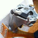
Forgetting the fact that the upper lens is not horizontally aligned by servo-coils like in traverse mechanisms,
I tried to remove it from the swing arm for further cleaning of the optical system.
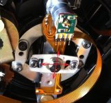
The upper lens is attached to a thin metal bracked that is fixed by two srews to the swing arm. (A black square sticks on the bracket)
After finding out that further disassembly is not possible, (the upper lens can not be lifted from the assembly)
I wanted to reassemble it, finding out that there is some horizontal play of
of the lens until the screws are tightened.
I had to fix it by the eye, trying to have it as much centered as possible.
How crucial is a centered position of the upper lens? Have not reassembled the CDM-1 yet to find out...
(Picture was taken after I put the lens back in)
Forgetting the fact that the upper lens is not horizontally aligned by servo-coils like in traverse mechanisms,
I tried to remove it from the swing arm for further cleaning of the optical system.
The upper lens is attached to a thin metal bracked that is fixed by two srews to the swing arm. (A black square sticks on the bracket)
After finding out that further disassembly is not possible, (the upper lens can not be lifted from the assembly)
I wanted to reassemble it, finding out that there is some horizontal play of
of the lens until the screws are tightened.
I had to fix it by the eye, trying to have it as much centered as possible.
How crucial is a centered position of the upper lens? Have not reassembled the CDM-1 yet to find out...
(Picture was taken after I put the lens back in)
Attachments
You will tell us. :-DHow crucial is a centered position of the upper lens? Have not reassembled the CDM-1 yet to find out...
I have shipped a CD960 in the post, and the reciever got a problem With the drawer mechanism. Two parts are loose in the player:
Does anybody recognize these parts?
An externally hosted image should be here but it was not working when we last tested it.
Does anybody recognize these parts?
Well - at least, it did no harm. Here is the full story:You will tell us. :-D
As I wrote before, I bought 4 used Philips CD-Players; CD-104 (2x)
CD-303 and CD304MKII. They share the same mechanism, CDM-1.
My first goal was to built a CD-transport prototype, based on the principle of the swing arm. Those players were meant as objects of study.
But though they gathered a lot of dust and moisture (one tinplate rusted to some deep grey with a surface like sandpaper) they work fine, besides the trays that get stuck a bit.
The CD-304mkII is capable to play defects on the surface of a disc summing up to 6mm without any clicks.
I decided, to keep the CDM´s and built my dream player, a top loader, using the CD-304 MKII´s viscerals.
Plus better DAC, ES 9018 based. Hope the casing will be finished in autumn.
Because the areas around the laser can be seen later, I decided to paint them in a dull black.
The chassis had to be shortened in height (about 3mm), one bracket, originally meant for the transport srew, had to go because of lack of room.
This meant disassembling and reassembling and realigning CDM-1.
Here are my findings:
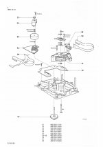
Before disassembling the CDM 1, one should know that one plate will have some play and needs to be realigned:
It is a metal plate, holding the lower bearing of the swing arm. It is mounted with two screws and washers to the chassis.
To reassemble everything, it should be easy to marl the area around the washers with a sharpie, but the washers have some play and are never centered.
Marking the area around the washers would be of no help at all.
I was too impatient to replace the screws with a design where the washer is implemented (not easy to find, M2.5 btw)
Anyway, with a screw without washer there is no play and marking the plate should be sufficient for reassembling.
But I did not do that and faced the BIG problem that the alignment of the swingarm according to the "optical" methods described in this this thread
and elsewhere on the net - CDM1 Laser Winkel einstellen just did not work!. Nada. Nothing.
I can see angles about 2° with the bare eye - but I saw nothing as described. The
requirement to fix your headwatch steady from a 45° angle to the setup seems impossible!
Maybe the designers of the CDM - 1 were fans of BDSM and did wear head harnesses for alignment...

Without putting mine in a vice at least- no chance.
The player did not even read the TOC
But there was still hope - the eyepattern and one assumption:
That designers never like to work with fractions. If the heads of the screws are sitting perfectly symmetrical in the mentioned plate, this should be a good starting point.
Et voilà, eyepattern, though blurry. I did not use washersonly the screws. The reason: Sliding the plate around to find the sweet spot will put the washers out of center.
Thus fastenig the screws will move the plate, one can observe it on the eyepattern.
I was very happy to have found the sweet spot at once - followed by the frustration that this clear eyepattern became blurred on other parts of the disc.
Up to a point, where the disc was unreadable..
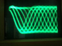
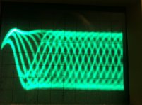
The false spot is when the eyepattern rises a bit in amplitude and becomes clear but also wavy - this point is too far.
The sweet spot is at a point, where the wavyness is almost gone but the eyepattern is still realitively sharp.
Not easy to find. With screws just a bit tightend to allow grip an movement at the same time, the plate can easily
slip from one maximium to the other.
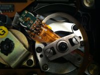
Working on the first tracks, the flex cables of the laer are in the way.
When finished, the waveform should look almost identical on the inner,middle and outer tracks.
I also noticed that another sign -or better sound - for the sweet spot is that the swing arm will make almost no noise when jumping between tracks.
Just some quiet and some chirp just before the track starts to play.
One very important thing about the center shaft of the swing arm:
It sits extremely tight between the bearings and gets easily stuck even when pulling it out gently. So there is no benefit from the M4 screw sitting at the bottom of the shaft.
When the screw gets fastened, the arm will get friction easily.
When reassembling, make sure the shaft is put all way through the bearings and tighten the bottom screw just with your fingers until you feel drag.
Check whether the swing arm bounces back and forth freely after gently kicking it. Secure the screw with paint.
Soemthing else: The CDM-1 was built to have both PCB mounted on it. But with the CD-104 and 304, one PCB is
mounted on the chassis of the player. It is lifted about 5-6mm. This bends the flex-cables unnecessarily in a vertical direction.
I mounted the PCB back on the CDM-1. But the screws need flat heads.
The overall horizontal derivation according to the focus signal is 80mV
between the first and last track. I will try to get this better.
The photos indicate that the sweet spot has not been met yet:
Or the upper lens I unfastened by mistake needs alignment as well...
The first eyepattern was photographed before disassembly, the second after reassembling and the described alignment. Looks a little bit more blurry.
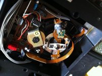
The third photo shows the reassembled CDM-1.
Attachments
Last edited:
Hi Salar,
It seems you invested a lot of effort in the CDM-1 (Mk-II ?), and perhaps you know more about it than the Philips engineers themselves
However I could not completely follow your description, especially the washers part and the marking and the symmetrical heads of screws. Could you attach some pictures for clarifying?
At the end you could align the metal plate holding the lower bearing, by tightening/loosing the screws, or by sliding the plate itself? And you got optimal result by watching the eye pattern, not by optical alignment? Could I follow this method without fully disassembling the unit, by only loosing the screws?
Hello scsazar,
watch the third photograph. You can see the markings around the screws.
But they were not precise because of the washers. The screws have diameter
2.5mm, the washer have 2.7mm inner hole. This is standard, but gives play.
Thus the plate 501 will move when fastening the screws. I just left the washers away. In the attached drawing only 1 screw and washer is shown.
I did only touch part 501, with screws fastened that much that the plate 501 can be still moved. Symmetrical means that the plate 501 sits in the middle
pf chassis 503. You can more feel it with your fingertips rather than seeing it.
You can follow the method without disassembly. If the swing arm is too stiff,
(it should bounce forth and back two times) just loosen M4 a bit.
Then loosen M2.5x6 completely and remove the washers, put M2.5x6 back
in and tighten them that much, that the Plate 501 can be still moved by some force.
But I strongly recommend to do this first:
Make sure that the two screws M2.5x6 are fastened. Remove the first screw carefully without touching and accidentally moving plate 501.
Remove washer. Put the screw back in and tighten it. Then do the same with
the second screw. You could also replace them with flange screws while doing so. Now mark a circle around the screw heads, with a thin pen.
The pen will always leave a tiny blank area between screw head and plate
as reference.
Doing this, you will have a precise marking as a starting point. Again: With washers it would not be precise. Do also mark the direction of the plate 501.
If you fail in aligning the arm in better than before, you can still return to
the original alignment
All the best,
Salar
BTW, CDM-1MKII is different:
http://www.hifi-advice.com/blog/spe...philips-cdm-range-of-swing-arm-cd-mechanisms/
Attachments
Last edited:
The false spot is when the eyepattern rises a bit in amplitude and becomes clear but also wavy - this point is too far.
The sweet spot is at a point, where the wavyness is almost gone but the eyepattern is still relatively sharp.
I have to correct this. I did try new screws with extra big heads - Din921, M2.5, length 6mm.
One should go to the point where the waveform is clear and wavy and bouncing. With my CDM-1, this meant pushing the plate to the left.
The big heads of the screws helped a lot in controlling the grip while moving the plate.
This is too far and caused the swing arm to stick in the most inner position,but not the most outer position.
Remember, i did loosen the screw of the bearings that the arm could bounce freely.
But this "point of sticking" is beyond the TOC - a point where the head would never move.
Easy to check: Without power, the head moves in center position, probably because of the force of the flex cables.
When I unplugged the power after the first seconds of the first track were audible, the arm would also swing to the center position.
Another proof that the "sticking point" is beyond the TOC and would not thread tracking.
But nevertheless I pushed the plate to the left until the arm would not get stuck.
I am talking about fractions of a millimeter here - a job better to be done by a potter or some blind samurai sword smith,
with almost no visible impact on the eyepattern. (It lost a bit of amplitude, barely to be seen literally)
I hoped to do this work with the player upside down, instead like working in a car repair shop on my back, the player set between chairs.
But focus seems not to be strong enough to overcome gravity.
I assume this must be ballpark now, with strange effects: A CD with artificial defects "CD-Check" from the Canadian company "Digital-Recordings" plays very well,
a battled and scratched Polygram CD from 1983 (first CD-plant in Europe) skips.
Also very interesting: The Sony YEDS-18 Test CD for player alignment is more wavy than a CD-R and some ordinary pressings from this millennium.
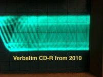
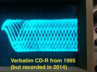
Also very interesting: A CD-R I bought for about $15 in 1995. (Not for 50pcs. For one CD), I found it unused in the cellar in 2014 and burned it.
On the Philips today, it shows a much better eyepattern than its successor from 2010.
Still, the Philips will not play the outer tracks of any burned CD-R without slight dropouts. Something to explore. BTW, I did not change any electrolytics yet or played with the tracking gain.
So I hope there are still some improvements to be made.
Some photographs of the eyepatters. I did lower the voltage to 1Vp-p as stated in the service manual.
Attachments


Last edited:
O.K, I think I found the solution for aligning the swingarm. No glass disc needed, no fluorescent tube, no mirror, no grid. Just a multimeter.
A scope would help as well but is not necessarily needed. But someone should confirm the following:
In the service manual´s chapter 4 "Mechanical Measurements and Adjustments " of all the players using CDM-0 and CDM-1, a resistor 3240 is mentioned.
It is on the main servo board (not on the CDM-0 / CDM-1 boards), and connected to the path leading to the focus motor of the swing arm.
This resistor connects to ground. Voltage measured across this resistor should be 0V - this means no offset in focus and correct turntable height.
But this means also: If the voltage is the same on the first track of a CD as on the last track, the swing arm is in perfect horizontal alignment.
And because horizontal alignment and tilt are related, tilt should be also zero.
Solder two wires to resistor 3240, measure the voltage on the first track and last track and adjust the swing arm´s plate until the voltages are almost identical.
I finally obtained around 8mV difference. Before it was more than 50mV.
You need to play with the plate´s screws a bit. Fastened enough for grip and still allowing movement. Again movement means fractions of a millimeter here.
I got to a point, where I even did not feel the plate moving with my fingers, but noticed the change on the multimeter.
A scope is for controlling sharpness of the eyepattern. But a sharp pattern should be a logical result anyway. Finally, the turntable height can be adjusted as well until 0V offset are obtained.
Finis - I hope!
Last edited:
Great information! I checked in the SM of Marantz CD-74/84 and CD-94. The resistor is 3.3R in both models, position is R240 on CD74/84, and R216 in CD-94. The SM of CD-74 mentions the voltage measurement method for turntable height adjustment, but nothing written about focus offset between the beginning and end of a disc. The SM of CD-94 has no mechanical adjustments section.
You´ll have to try out. I think pushing left -with the font panel facing to me- was a good starting point to me. It is a little bit pushing, a little bit turning.
Took me almost an hour to find the sweet spot. At least I could not do the work with the player upside down like in your photo.
The player has to stand in normal position between chairs or piles of books
Took me almost an hour to find the sweet spot. At least I could not do the work with the player upside down like in your photo.
The player has to stand in normal position between chairs or piles of books
Last edited:
You need to move the laser along the two imagined lines:
a) one that connects start and end positions of the pickup, as they have to be in the same plane, i.e. at the same distance from the disc surface
b) line that connects the pickup midway position to the pickup axis center.
The start, midway and end position would form a triangle in which each corner point should be on the same plane or at the same distance from the disc.
Departing from this, determine which moves of the shin would accomplish this.
P.S. "With patience, arm yourself".
CDM12.1 has nothing to do with CDM-1. Completely different design.I want to ask,where can i find good quality laser replacements like cdm12.1?
Besides ebay I do not know sources. The company selling CDM-mechanisms on
behalf of Philips, Daisy Laser ceased to exist more than five years ago.
Τα πάντα καλό,
Salar
- Status
- This old topic is closed. If you want to reopen this topic, contact a moderator using the "Report Post" button.
- Home
- Source & Line
- Digital Source
- Philips CDM-1 swing arm alignment