Help please...
Some time ago I purchased Scott Nixons dac kit (2.5 v) pcb board, cs8412 and some TDA1543 dacs.
I have not started to build yet, since I have been working on a phono pre lately.(And things take time ). Now the riia is done and I`m satisfied (for a while). Well enough blah blah....
As far I understand the non os dac with a passive I/V gives an inverted audio signal. Doing this would make the dac very difficult to use considering my other sources.
Does using an op amp for active I/V degrade the sound in a big way??
How about the circuit that Kuei Yang Wang designed with opa660, does that one give a noninverted audio signal?
Hope you understand my problem?
Some time ago I purchased Scott Nixons dac kit (2.5 v) pcb board, cs8412 and some TDA1543 dacs.
I have not started to build yet, since I have been working on a phono pre lately.(And things take time
). Now the riia is done and I`m satisfied (for a while). Well enough blah blah....As far I understand the non os dac with a passive I/V gives an inverted audio signal. Doing this would make the dac very difficult to use considering my other sources.
Does using an op amp for active I/V degrade the sound in a big way??
How about the circuit that Kuei Yang Wang designed with opa660, does that one give a noninverted audio signal?
Hope you understand my problem?
TDA1543 IV Stage
Hi Chris,
If you search the archive you will find many followers of different believes:
Passive IV conversion, various schemes by Rudolf Broertjes and Thijs, and Jocko using a common base amplifier (input going to the emitter ), Opamp IV with virtual ground at the non-inverting input, me and Chris Owen of Ack Dack, and so on and so on.
I don't remember a working solution with the OPA660 and the TDA1543.
One of the least important issues is if the DAC inverts phase or not. I can't hear that, but others will vigorously disagree.
I can't hear the effect of the Grunge Buster CD mat, green or black pens, green, red or blue lights shining light on the CD, Bedini Ultra Clarifier, dampening of the case of the player, placing stripes of paper on the CD or placing square pieces of paper on my loudspeaker, knocking the energy out of my speakers with my bare fists, demagnetisizing my system with a XLO CD (the noises frighten my neighbours), placing pyramids at strategic locations in my room, placing the speaker cables on large pieces of porcelain to "isolate" them, hanging Dr. Boner's "polycylindrical surfaces" at the ceiling, placing the Magic Brick on top of equipment or on the transformer, Jon Risch's famous sandbag trick: placing a bag of canary sand over the crystal of the CD Player, dampening said crystal with chewing gum, poster buddy or blue tack, multileadcoils in a loudspeaker crossover, rounding off corners on PCB's, "burn in effects", varous sharp cones supporting my equipment and damaging my furniture, etc. etc.
I agree with that one
Also how could You tell the original recording fase (inverted or not). I think none of us don't know the real fase of the recorded signal. (only maybe a few of us that have Van den Hul's fase meter's or how U call that devices)
Also is Your amp inverted or not.
My opinion don't worry about it very much. I have dac that inverts fase and it works just fine. I am still working on it but it is good.
happy diy-ing
daniel
Yes, it inverts the phase. But it is not directly applicable for the TDA1543.Chris said:How about the circuit that Kuei Yang Wang designed with opa660, does that one give a noninverted audio signal?
Pedja
I can easily hear the difference if I reverse speaker cables polarity.
This could actually be a solution to your question. If you have sources which reverse phase and which not, you might put a swith at amp' output, providing normal polarity, reversed polarity and speakers off. I wouldn't mind having such a switch on my amp
This could actually be a solution to your question. If you have sources which reverse phase and which not, you might put a swith at amp' output, providing normal polarity, reversed polarity and speakers off. I wouldn't mind having such a switch on my amp
Chris said:dfsgdfgfdnhf
,.b.bjk.
That was what I wanted to tell them too.
I tried your solution but I discovered it is not active and my DAC sounded weird with it connected to it as I/V converter
edit: Mmm, you edit your posts faster than my eyes can move; I swear I saw a turntable pickup just a minute ago.
jean-paul said:
That was what I wanted to tell them too.
Sorry about that!!! some problems attaching an image

jean-paul said:
edit: Mmm, you edit your posts faster than my eyes can move; I swear I saw a turntable pickup just a minute ago.
No really!! that can`t be right ??????
Well I had some problems posting the schematic, and yes the pickup was there for a short moment....
What`s wrong with the schematics? (I`m not an EE so you have to, or could at least try to forgive me
Peter Daniel said:This could actually be a solution to your question. If you have sources which reverse phase and which not, you might put a swith at amp' output, providing normal polarity, reversed polarity and speakers off. I wouldn't mind having such a switch on my amp
Hmm, I like that idea
. Thanks Peter..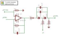
Re: TDA1543 IV Stage
You forgot what may well have been the tweak of tweaks, the Tice Clock not to mention Mbongo dots, Shakti Stones and Elephants feet.
On the subject of I/V , ever tried the ECC88 with cathode drive?
ray.
Elso Kwak said:Hi Chris,
If you search the archive you will find many followers of different believes:
Passive IV conversion, various schemes by Rudolf Broertjes and Thijs, and Jocko using a common base amplifier (input going to the emitter ), Opamp IV with virtual ground at the non-inverting input, me and Chris Owen of Ack Dack, and so on and so on.
I don't remember a working solution with the OPA660 and the TDA1543.
One of the least important issues is if the DAC inverts phase or not. I can't hear that, but others will vigorously disagree.
I can't hear the effect of the Grunge Buster CD mat, green or black pens, green, red or blue lights shining light on the CD, Bedini Ultra Clarifier, dampening of the case of the player, placing stripes of paper on the CD or placing square pieces of paper on my loudspeaker, knocking the energy out of my speakers with my bare fists, demagnetisizing my system with a XLO CD (the noises frighten my neighbours), placing pyramids at strategic locations in my room, placing the speaker cables on large pieces of porcelain to "isolate" them, hanging Dr. Boner's "polycylindrical surfaces" at the ceiling, placing the Magic Brick on top of equipment or on the transformer, Jon Risch's famous sandbag trick: placing a bag of canary sand over the crystal of the CD Player, dampening said crystal with chewing gum, poster buddy or blue tack, multileadcoils in a loudspeaker crossover, rounding off corners on PCB's, "burn in effects", varous sharp cones supporting my equipment and damaging my furniture, etc. etc.
You forgot what may well have been the tweak of tweaks, the Tice Clock not to mention Mbongo dots, Shakti Stones and Elephants feet.
On the subject of I/V , ever tried the ECC88 with cathode drive?
ray.
Re: Re: TDA1543 IV Stage
Hi ray,
Actually I did not try the Shakti Stones, and the other tweaks you suggested.
I am not into tubes...
rfbrw said:
You forgot what may well have been the tweak of tweaks, the Tice Clock not to mention Mbongo dots, Shakti Stones and Elephants feet.
On the subject of I/V , ever tried the ECC88 with cathode drive?
ray.
Hi ray,
Actually I did not try the Shakti Stones, and the other tweaks you suggested.
I am not into tubes...
Re: Schematic error....
Hi Chris,
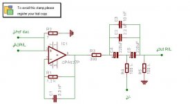
I can't see much wrong, except orientation of electrolytics. It is very much like the TDA1543 datasheet.
With +5V supply for the DAC I am using R2= 3k3.
Do you need that large output caps? I mean the electrolytics. The opamp has low output impedance and you could lower R3. I am using OPA 604 instead of OPA627....And an 0.47µF Audio Note paper in oil copper foil.
Chris said:This should be more correct..?
Please, what else is wrong? I can handle it!
Hi Chris,
I can't see much wrong, except orientation of electrolytics. It is very much like the TDA1543 datasheet.
With +5V supply for the DAC I am using R2= 3k3.
Do you need that large output caps? I mean the electrolytics. The opamp has low output impedance and you could lower R3. I am using OPA 604 instead of OPA627....And an 0.47µF Audio Note paper in oil copper foil.
Re: Re: Schematic error....
Thanks Elso and others...
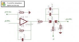
Yes the circuit is mostly from the tda 1543 datasheet. Would you change it in any way to improve it (R1,C1)?
R3= how low?
Why is it not active(no ref to ground in feedback loop?)?
Only high quality 0,47 uF cap at the output sounds good.
Thanks
Chris
Elso Kwak said:
Hi Chris,
I can't see much wrong, except orientation of electrolytics. It is very much like the TDA1543 datasheet.
With +5V supply for the DAC I am using R2= 3k3.
Do you need that large output caps? I mean the electrolytics. The opamp has low output impedance and you could lower R3. I am using OPA 604 instead of OPA627....And an 0.47µF Audio Note paper in oil copper foil.
Thanks Elso and others...
Yes the circuit is mostly from the tda 1543 datasheet. Would you change it in any way to improve it (R1,C1)?
R3= how low?
Why is it not active(no ref to ground in feedback loop?)?
Only high quality 0,47 uF cap at the output sounds good.
Thanks
Chris
Attachments
Re: Re: Schematic error....
Hi Elso, how do you figure the (3K3) value for R2? I want to try this IV stage, but I'm having a hard time understanding this current business. If you (or someone else) could spell it out for me, please?
Elso Kwak said:
Hi Chris,
I can't see much wrong, except orientation of electrolytics. It is very much like the TDA1543 datasheet.
With +5V supply for the DAC I am using R2= 3k3.
Do you need that large output caps? I mean the electrolytics. The opamp has low output impedance and you could lower R3. I am using OPA 604 instead of OPA627....And an 0.47µF Audio Note paper in oil copper foil.
Hi Elso, how do you figure the (3K3) value for R2? I want to try this IV stage, but I'm having a hard time understanding this current business. If you (or someone else) could spell it out for me, please?
Re: Re: Re: Schematic error....
Hi Mad_K,
I put a pot a Vref and observed a 0dB sine wave on the scope. With a low value of the pot I could null the offset at the output but the sine wave was distorted. With some safety margin I got at 3k3 for the least offset and a undistorted sine wave. I also found the 3k3 resitor in Philips players using the TDA1543. The value is not given in the datasheet. Also note this is for +5V supply and using active IV-conversion as in the datasheet. If you connect the non-inverting input of the IV-opamp to ground, and not to Vref you get much more offset. I have about -1.6V DC before the output caps. Note I am using an inverting output buffer
Mad_K said:
Hi Elso, how do you figure the (3K3) value for R2? I want to try this IV stage, but I'm having a hard time understanding this current business. If you (or someone else) could spell it out for me, please?
Hi Mad_K,
I put a pot a Vref and observed a 0dB sine wave on the scope. With a low value of the pot I could null the offset at the output but the sine wave was distorted. With some safety margin I got at 3k3 for the least offset and a undistorted sine wave. I also found the 3k3 resitor in Philips players using the TDA1543. The value is not given in the datasheet. Also note this is for +5V supply and using active IV-conversion as in the datasheet. If you connect the non-inverting input of the IV-opamp to ground, and not to Vref you get much more offset. I have about -1.6V DC before the output caps. Note I am using an inverting output buffer
- Status
- This old topic is closed. If you want to reopen this topic, contact a moderator using the "Report Post" button.
- Home
- Source & Line
- Digital Source
- TDA 1543 I/V stage education needed!!