Hey,
Since I have Tibi's Shiga reborn, I also plan to give the original (JVC) Shigaclone to my brother. There seems to be somewhat tight space between the laser and the board. Do you happen to have some pictures of the laser mods in the original Shigaclone?
Thanks!!
Modifications are the same. Follow this thread and you'll get all relevant info.
Regards,
Tibi
To BMW850, did you ever get this sorted out??
I have noticed the same sound coming from my Shiga but it seem to be static electricity but I can't pin point why and how....
This issue may be related to ground loop, digital out is reversed (ground with signal), one of V1..V4 regulators is oscillating. Add 47uF - 100uF after regulators.
Regards,
Tibi
I have done the moddings recommended and all the time I have been positively surprised but today I hit rock.
I installed V3 and V4 with lt 1085-50 and the whole sound image changed, from a solid wall that has only gotten wider and bigger by every change, into the speakers. What a bummer!
I hope it will change back to the wide room again when it has been running for a number of hours but it was a real disappointment for ones.
I don't know if it will improve if I change V1 and V2 also but I get that impression from what they are regulating.
Tomorrows work, now si work all night.
There is a big chance that your LT1085-5 oscillate. Add on the regulator pins 100uF/6.3V oscon/polymer or tantal.
Regards,
Tibi
... Add on the regulator output pins 100uF/6.3V oscon/polymer or tantal.
Regards,
Tibi
Hi Tibi and all builders,
New issue. I had issues arising from CD ribbon cable connector on start up. It had a very box shaped and I thought it was just a more enclosed FFC connector. Wrong! So I had another unmodified deck that was definitely FFC. It works! Had a full day of normal operation. But now the deck is shutting itself off after a minute or so of playing like the off switch was hit. Goes to home and displays number of tracks. Will start replaying with start. Also outer tracks having tracking issues also. Ribbon cable I surmise. My original breadboard was off 3 ribbon slots so I re-aligned, I have tried lots of height adjustments from PCB to deck, and many distances between them. 3 different cables also. I have ordered some new molex premo extra flex FFC. Any other ideas what may be causing this behavior?? Made a new motor cable also just for completeness. Stock unmodified deck. Thanks for any input!
best regards,
Steve
CD Format
Tibi,
I have a question that I don't find the answer to in direct words so could you please help out.
I tried playing a HDCD this evening but the Shiga Black MkII refused to read TOC on this HDCD. I understand that the Quantum is playing all formats both HDCD, SACD and so on, is there any difference in the Quantum towards the Shiga Black MkII that I have regarding CD Formats??
I understood that the Shiga also read all formats and if yes, then come the second question, why do my Shiga refuse to play my HDCD??
By the way, I did change all V1 to V4 and added some 100 uF tantalum to all regs and now I am happy, sound is refined and back to "normal" with the whole 3D stage again and yes, it was missing the tantalums. Most likely I had oscillations in one, two or all of the regulators but not any longer.
It is time to aquire an oscilloscope cause I am not able to see such things but I do hear them.
Last step is to get the Tentlab clock and feed it from a Reflektor D instead of the LT1085 and get a deasent C8 Cap. I took what I had at home to put the Shiga together so I could start evaluating it but I only had older type Clarity caps at home and of cause only 0.22 uF so I had to put two of them in serie to get 0.11 uF, close enough to the stipulated 0.1 uF Mundorf so I will most likely gain a little more music from a Cap change also but I am over all very happy with my new toy.
There are some consistent differences between Quantum and Shiga, but both will read same formats.
HDCD decoding is made in DAC, not transport.
If your DAC is capable of HDCD decoding, than you'll hear it.
Check if your disk is scratched at TOC, or is dirty.
An work around is to use a disk that have at least same number of tracks as your HDCD and the TOC is read by Shiga. Than play your HDCD without pressing the TOC.
Regards,
Tibi
Hi Tibi,
So in trying to figure out why my disc just stops I have been monitoring LDD at 2N4403 and I am observing that the voltage drops slowly all the time. So I have swing to turn laser on and I have 4.75 after TOC and 2.763 vdc to play. This voltage drops to 2.62 range and player stops. Now I have 4.4 vdc TOC 2.63 vdc to play, and 2.63 starts dropping. This cycle just continues so I watched vdc at idle and they keeping dropping also. Should I replace this transistor or is it secondary to some other event? PS stays rock solid at 5.08 Vdc. Work has kept me from having time to get images I will try to get some to you. Thanks!
best regards,
Steve
Hi Steve,
Yes, the board will work just fine with AD151-2,5V reference in place, but will not bring expected sonic improvement.
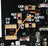
You need to mount only U5 and C69, cut the U5 output trace immediately after U5 output. Remove L1 bead and grab a wire from U5 output to C11. On C11 mount a 10uF tantalum or oscon in parallel with a good quality 1Kohm resistor - preferably a metal foil one.
This mod will provide a very clean 2,5V reference to pin detector.
You'll love instrument extension and decay after this mod.
Quantum ultra high-grade have this mod inside, It was compared with players above 18000eur and now used as reference along some very big names.
Regards,
Tibi
Greetings Tibi
Just playing with my toys again. Now have Dueland Cu foil in C8 and finally got the smd resistors so that I could implement the LT1086-adj in the PSU.
Also have parts for this ADP151 mod.
Currently C11 is 1nf silver mica.
From the earlier post describing this mod you give C11 now 10uf tant in parallel with 1k metal film. So take out 1nf silver mica?
Which side of C11 should U5 output go? Next to L1 or next to C69?
Thanks
Hello,
Note that ADP151 must be 2,5V one.
Please keep C11 in place. C68=10uF tantal is there to ensure ADP151-2.5 stability.
1K is also there to give ADP151-2.5 a slight load.
U5 output is over C68. Measure, do not mount components in "blind".
Regards,
Tibi
Greetings Tibi
Just playing with my toys again. Now have Dueland Cu foil in C8 and finally got the smd resistors so that I could implement the LT1086-adj in the PSU.
Also have parts for this ADP151 mod.
Currently C11 is 1nf silver mica.
From the earlier post describing this mod you give C11 now 10uf tant in parallel with 1k metal film. So take out 1nf silver mica?
Which side of C11 should U5 output go? Next to L1 or next to C69?
Thanks
Also mounting new caps to C11 which side should be the negative?
Also mounting new caps to C11 which side should be the negative?
Please use a multimeter in continuity mode. Negative side of C11 is connected to ground. Ground is connected to LA6541 heatsink as well. This way I'm sure you'll mount correctly.
Regards,
Tibi
Please use a multimeter in continuity mode. Negative side of C11 is connected to ground. Ground is connected to LA6541 heatsink as well. This way I'm sure you'll mount correctly.
Regards,
Tibi
Thanks for not spoon feeding - means that I learn
Was trying to refer to schematic that you shared in old ivc shigaclone but realised it was not matching up with the Shiga Mk2
Last edited:
Hello,
Note that ADP151 must be 2,5V one.
Please keep C11 in place. C68=10uF tantal is there to ensure ADP151-2.5 stability.
1K is also there to give ADP151-2.5 a slight load.
U5 output is over C68. Measure, do not mount components in "blind".
Regards,
Tibi
Yes ADP151-2.5
I got the U5 output by referring to datasheet.
But now I am a bit confused.
1nf silver mica stays in C11 - tick
10uf goes in C68 (SMD)? not on same pads as C11 as seemed to indicate in that quoted passage from earlier?
1k resistor is this R65? or simply across legs of 10uf?
C68 = 10uF SMD tantalum or ceramic and is not on the same pads as C11
C68 ensure ADP stability and must be close to chip.
R65 = 1K and by design is across C68 you just place the resistor where is noted on PCB
Yes, cut trace after U5 output. Multimeter is your friend here.
Regards,
Tibi
C68 ensure ADP stability and must be close to chip.
R65 = 1K and by design is across C68 you just place the resistor where is noted on PCB
Yes, cut trace after U5 output. Multimeter is your friend here.
Regards,
Tibi
C68 = 10uF SMD tantalum or ceramic and is not on the same pads as C11
C68 ensure ADP stability and must be close to chip.
R65 = 1K and by design is across C68 you just place the resistor where is noted on PCB
Yes, cut trace after U5 output. Multimeter is your friend here.
Regards,
Tibi
OK something not happy - does not read TOC
when L1 is in place it does - so something not g=right with my implementation of movie.
please see my picture to see if I have everything correct. thanks. (obviously this image presumes ADP151 is also added)
not sure about where I have the cut trace? this is the only trace I see from output. >> between U5 output and C68.
No continuity between that output tab and that capacitor pad
that cut doesn't make any sense to me. how does it stabilise ADP151 if there is no connection? is it the other trace that comes out after the C68 pad and runs down a short way under the U5 label to the via? but that looks like it goes to somewhere on the LA9242
Attachments
Last edited:
- Home
- Source & Line
- Digital Source
- Shigaclone MKII Black - The builders Thread