Freds correct, they are very flexible in the East - thats why almost everything is manufactured in China these days.
8 Years ago it was hard to find a good SMD subcontrator in China, now I vist factories with 150 SMD machines in a row! 20K Pcs. of anything is less then a couple of days work to these guys!
Many thanks for the buffer circuit; I took the liberty to redraw and combine the XO & Buffer the circuits. Do you have a description of the adjustment function of the various Pots?
Does anyone have modern SMD transistor replacements for the following devices (lower noise would be preferable) - The MRF is already very low noise: -
2N4957 PNP
Max. VCE 30V
Max. IE. 30mA
Max. Diss. 200mW
Hfe / Gain 17dB @ 450MHz
Max Freq. 1.6GHz
Noise Figure 3dB @ 450MHz
MRF904 NPN
Max. VCE 15V
Max. IE. 30mA
Max. Diss. 200mW
Hfe / Gain 11dB @ 450MHz
fT 4GHz
Noise Figure 1.5dB @ 450MHz
Attachments
JohnW said:
Many thanks for the buffer circuit; I took the liberty to redraw and combine the XO & Buffer the circuits. Do you have a description of the adjustment function of the various Pots?
Does anyone have modern SMD transistor replacements for the following devices (lower noise would be preferable) - The MRF is already very low noise: -
2N4957 PNP
Max. VCE 30V
Max. IE. 30mA
Max. Diss. 200mW
Hfe / Gain 17dB @ 450MHz
Max Freq. 1.6GHz
Noise Figure 3dB @ 450MHz
MRF904 NPN
Max. VCE 15V
Max. IE. 30mA
Max. Diss. 200mW
Hfe / Gain 11dB @ 450MHz
fT 4GHz
Noise Figure 1.5dB @ 450MHz
Schematics seems OK to me. Note that the cheap BFS17 (Philips) I used is mine. Matthys' original is a MMT3960.... Couldn't find its characteristics on the web, so I'm not sure BFS17 is the right choice here, but it works... NF of BFS17 is not quite nice (6dB/250MHz if memory serves)
Tried to find equivalent BJTs in SMD, but very very hard to find something with NF as low as 1.5dB without having megabucks... Seems to me that Philips BFR92 (NPN) and BFT92 (PNP) could be a good choice...
By the way, I'm not sure nice NFs and nice linear chars are mandatory for the buffer. Wideband switching BJTs should be enough here. I have the PNP PMBT3640 from Philips in mind, or the MMBT3640 from OnSemi. Fairchild's MMBTH81 too... Dunno...
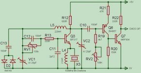
Adjustments in the XO are not obvious, but the L5/VC1 is dimensioned to operate just above resonance (Matthys dixit), and provides a phase shift of 120°. The C11 cap plus the resistor (R13 + VR1 (50K, not 100K)) adds a 60° phase lag, and finally the BJT adds a phase reversal (180°), closing the 360° loop... The "output" variable cap VC2 is used to tune out the shunting effect of L5 on R12 (load resistor).
Practically, I just tuned the adjustments to have the max amplitude at the right frequency...
And IMHO, RV2 is just a threshold level adjustment...
Last note from Matthys (hope you have your book soon, it'll all make clear), Q3's Hfe must be high (100) for the circuit to work. I know the BFS17 I used has a min Hfe of 60, but it worked...
OK, Frank....
Let's say that you are right, and he does find someone who wants to use 20,000 xtals/year.....
SC cut......
At 100 MHz.....
With a ludicrous phase noise spec......
And they don't think that it is such a good idea that they steal it from him and go out and make them without him..........
Why is he asking us to help design it for him......?
For free.......?
So that he can make money at it?
Great, just what the forum needs......another Lars.
Jocko
Hi Cheff,
Cheers for the info, your right its not really clear what’s going on – especially with VC2 and RV1.
I searched the net, and found some interesting devices from Infineon. Planning to try the BFG235, it’s a low noise 2.7dB @ 60mA, 2W Transistor. “Large transistors with high Ic max used at low currents have best 1/f performance” – SIEMENS App Note #23
I guess the 1/f noise of the resistors will be the biggest noise source at LF in the buffer circuit – its kind of a balancing act between resistor noise and transistor Ic current – transistor noise increases as Ic increases.
I’ve also tried to find data on the MMT3960 with no luck, also tried MMT3960A, MMBT3960, MMBT3960A, 2N3960 & 2N3960A – but all too no avail. I did find a data sheet on the 2N3960 from Semicoa Semiconductors - but has only the bare basic information.
So I guess it will be Plug & Play Time....
Decided against the simple MC100LVEL14 due to, and I quote from EuroQuartz “Crystal theory” technical notes: -
“Cascade logic circuits, may show an appreciable lagging phase shift at the operating frequency. Even worse, is that in some circuits due to many non-linear active stages within these amplifiers, the lag is not constant over the operating cycle. The result is poor short-term stability or jitter.”
Well there you have it – I’m certainly not taking the risk! If the MC100LVEL14 had a simple internal path maybe, but there’s a selector in the path as well…
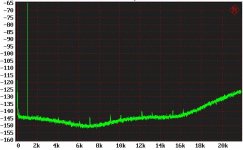
An update on the TI5015 modulator - I’ve improved the master Clock to the modulator, which as a result has lower the noise floor. By observing the 3 “humps” on the noise floor - you can clearly see that TI has adjusted the Poles and Zeros of their noise shaper to spread the feedback power over the audio band. This explains the excellent 19KHz / 20KHz 3rd order IMD @ -115dB – better then any amplifier - Analogue or Digital that I’ve measured. 
Dynamic range Awtd is now 114dB and THD @ 1KHz 0dB is 0.00004% - all this at 384KHz PWMFs – very impressive!
I found that a good test of the clock phase noise performance is to observe the Single Ended noise floor with the modulator Muted – i.e. with a 50:50 output Duty Cycle. While this will not reveal any clock modulation due to cross coupling while the modulator is operating, it does give an indication of the basic phase noise performance of the clock.
Due to the poor stop band rejection of this modulator – I recommend anyone who wishes to implement it, to up-sample to 200KHz with TI’s 4192 SRC, and thereby gain the advantage of the 4192’s 140dB+ stop band rejection.
Below is a 16K FFT @ -60dB Ref. 0dB – with the improved clock – notice the three “humps” on the noise floor.
Attachments
Hi John,
congratulations on your achievement! I hope you wouldn't mind another question. I assume you used discrete Pierce oscillator, but did you fed sine clock output from oscillator directly to the clock input of TAS5015, or did you use any type of comparator in between? I would like to know how transition time of the clock signal affects jitter. On first look I would say faster the transition times, less jitter. But what if this jitter maps outside the audio band?
Best regards,
Jaka Racman
Hi Jaka,
First, Pls. let me clarify that I was congratulating TI on a job well done – and not congratulating myself!
I wish I could say that I’d constructed my own oscillator – but alas, I found an old XO module in my Lab – with superior performance to the original.
If you look closely at any Phase Noise plot you will see that usually, the worst noise is close in to the carrier, so the greatest Jitter is normally always in the audio band - adding any kind of Buffer / Comparator will not help. CMOS devices have very poor LF noise – if LF noise is important then its better to use large transistors with high Ic Max - used at low currents, taking into consideration that there fT will drop at lower operating currents.
If your clock circuit outputs a Sign wave, the best you can do is add a high gain buffer constructed with low noise transistor – such as posted above by Cheff. If Low Phase noise is important – never feed a Sign wave into a logic device.
With digital, it’s always best to have the fastest Rise / Fall time clock you can. This allows the clock to transverse the logic level transition points in minimal time – which minimises the “period of uncertainty” as to when the logic should switch from one binary state to the other – this “uncertainty” degrades the circuits phase noise.
Maybe you could give Pletronics
a whirl, they make some low-jitter clocks with LVDS/LVPECL outputs. I use them for driving high-speed (3.125 Gbps) SERDES clocks.
a whirl, they make some low-jitter clocks with LVDS/LVPECL outputs. I use them for driving high-speed (3.125 Gbps) SERDES clocks.
JohnW said:As an audio designer I get to travel all over the world working with OEM’s, and on the other side of the coin, work with semi-conductor manufactures designing the chips that go into these very products.
Of all the companies I work with these days – None and I mean NONE! have anything close to a decent auditioning room & system. Most places I go into, your lucky to even find a pair of matched speakers.
In the semi-conductor industry, nobody seriously listens to there own products, preferring to “listen to measurements” – don’t even try to mention Capacitor sound!
I walk around these companies, and hear comments like “Why bother you can’t hear below –100dB anyway”. I walk past without passing remark – but become more disillusioned, as I know anything I say will “fall on deaf ears” – no pun intended!
So, do I stop working in this industry? No - with the Do-It-Yourself-Audio forum, I’m willing to share my knowledge and designs, and help where I can (and ask for help) – for I know that I’m with others who are truly interested in Audio, and in advancing the art of Audio. I’m with others, whose most important piece of measurement gear – comes down to their very own ears!
Don’t get me wrong, I don’t believe there’s any excuse for a poor measuring system, but that said – the day I hear a Digital system sound as good as a high quality Turntable playing though a Valve OTL amp driving ESL speakers directly, will be the day that I can say Digital has finally delivered on its promise.
So I hope I don’t offend, as a professional in a Do-It-Yourself-Audio forum")
Hi John,
This thread is certainly very interesting.
WRT your 100MHz XO I believe you might try and speak directly
with Wenzel & Assoc, as posted elsewhere here. They appear
to have the lowest phase noise oscillators available at this
present time. I have checked many websites spoken to many
XO manufacturers and Wenzel are pretty much it. Why re-invent
the wheel?
Moving on... your results with modulators is encouraging, however, I am interested if this has a direct parallel with
audio AD converters. Currently the best 1 chip solution is
AKM AK5394 which has 123dB DR (A-wtd). In your experience
dealing with audio chip makers, is this likely to improve any time
soon?
Cheers,
Terry
Hi Terry,
AKM have done a very good job at 123dB “Awtd” I’ve been thinking of upgrading the ADC’s in my AP, as I’m reaching currently “Measuring in the noise” with my current set-ups.
One thing to be concerned about is the “Noise on the left Channel” that AKM mentions in the data sheet – and “cure” by adding a DC offset, sounds like problems with idle tones.
To achieve over 120dB Dynamic range on silicon is an extremely good design. In silicon, you don’t have the luxury of large capacitors, nor can you afford the luxury of a large amount of “Large” transistors to achieve low 1/F noise. Also, if you’re constrained to a CMOS only process, you’re really have the “short end of the stick”! I wonder if AKM use a duel die chip?
For better analogue front-end performance, it’s much easier to design with discrete components, and then leave the decimation to a VLSI digital chip. I can’t see an integrated ADC getting much better, maybe one day we will see a 128dB ADC – but I’m not going to hold my breath until then…
All my DAC designs use external re-latching and clocking to achieve the results I’ve mentioned. In-fact, are very similar in concept to the Pink Triangle DACAPO of 10 years ago, which achieved it’s remarkable audio quality, due the extremely low jitter of its clock - a fundamental requirement for its One Bit discrete DAC design – way before “Jitter” was understood and "popular talk" in the audio industry.
Its easier these days with the availability of “Single Logic Gate” families – due to their tight packaging, this results in very low internal lead inductances. These “Single Logic Gate” families have, the best Phase Noise performance of any CMOS / TTL logic family that I’m aware of.
As digital modulators have improved, I’ve had to start to use ECL logic to make the best use of these modulators performance. I’m working with a modulator that has a 140dB dynamic range - at least in the digital domain! – It remains to be seen how good I can make the “Analogue” back-end. By “Analogue”, I mean the Clocks, PSU’s and Latches… anything that will introduce Phase Noise on the modulators PWM data.
Re: Re: Reference
Hi Cheff,
are you talking about my hand-drawn little circuit? What has your optimization been like? Mine's been running for a while, and I must admit I have not ventured into discrete designs.
Some of the things said in the Euroquartz book I summarized still puzzle me, i.e. why a low fT transistor would be beneficial (which means low Q because of low amplification) and why a JFET would be superior (also low LF noise, but much higher bandwidth).
Regards,
Eric
CheffDeGaar said:
Absolutely, and more exactly it's entitled "Emitter coupled XO". Mentionned as "outstanding" by Matthys, in terms of short term stability. I shamelessly borrowed this circuit from this thread.
Hi Cheff,
are you talking about my hand-drawn little circuit? What has your optimization been like? Mine's been running for a while, and I must admit I have not ventured into discrete designs.
Some of the things said in the Euroquartz book I summarized still puzzle me, i.e. why a low fT transistor would be beneficial (which means low Q because of low amplification) and why a JFET would be superior (also low LF noise, but much higher bandwidth).
Regards,
Eric
JohnW;
following up on your search for low 1/f noise transistors; www.chic.caltech.edu/Publications/phase_tutor.pdf
suggests that circuit topology can greatly reduce the converson of 1/f amplifier noise to close in phase noise
also www.vectron.com EMXO series may be a price/performance winner, if still too expensive for consumer electronics @ ~ US$100 in 5K qty for a vacuum canned, SC cut, ovenized xtal osc
several sources suggest that the the superior phase noise properties at lower oscillator freq makes multiplying up a 5-10MHz standards class osc gives lower close in phase noise
xtal acceleration sensitivity also enters into the phase noise eq as you push electronic noise sources down
Thanks for all the info.
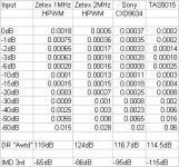
Just a quick posting, of THD, Dynamic Range "Awtd" and 19KHz / 20KHz 3rd Order IMD results of 3 Modulators.
The Zetex 2MHz HPWM Dynamic Range result is limited by Phase Noise, the others might be about 1dB to 2dB worst due to Poor Phase noise performance of LVDS TX / RX I used on my Eval Bd.
Just a quick posting, of THD, Dynamic Range "Awtd" and 19KHz / 20KHz 3rd Order IMD results of 3 Modulators.
The Zetex 2MHz HPWM Dynamic Range result is limited by Phase Noise, the others might be about 1dB to 2dB worst due to Poor Phase noise performance of LVDS TX / RX I used on my Eval Bd.
Attachments
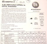
Another way of ....
... converting the sine wave signal from a crystal oscillator, to square waves, that can be transferred jitter free to a digital circuit.
The MC100EPT21 is a (balanced) PECL to TTL converter, or in other words a balanced comparator that converts a small analog signal to a square wave output.
Look at the jitter data, and speed .....
Attachments
Re: Another way of ....
Never did like using a comparator for XO -> TTL, they suck.
I think a clipped transistor circuit is better however this looks
V good. Do they do a 5V TTL version?
Terry
Lars Clausen said:... converting the sine wave signal from a crystal oscillator, to square waves, that can be transferred jitter free to a digital circuit.
The MC100EPT21 is a (balanced) PECL to TTL converter, or in other words a balanced comparator that converts a small analog signal to a square wave output.
Look at the jitter data, and speed .....
Never did like using a comparator for XO -> TTL, they suck.
I think a clipped transistor circuit is better however this looks
V good. Do they do a 5V TTL version?
Terry
Hi Scott,
Thanks for your reply, your right that the specification requirements are very high, but I’ve just checked the specs for the HP10811A/B 10MHz Quartz Crystal Oscillator (this is an OVEN unit), and they quote –120dBc /Hz at 10Hz and –160dBc/Hz @ 10KHz. This unit is not renowned for its short-term phase noise.
The fact that this is an oven unit has very little to do with its short-term stability (Phase Noise) – but more to do with its Longer-Term Frequency Stability.
As I’ve said earlier, “Off The Shelf” commercial grade Crystal Oscillators, VCXO’s and OCXO’s are more often then not, based on IC oscillator / PLL building blocks - and as a result have poor Phase Noise performance - as you also have discovered and highlighted.
Simple discrete designs (based on Butler or Colpitts oscillators), while not possessing the Long-Term Frequency Stability performance, can be designed to meet the short-term Phase-Noise – at a consumer price point ($2 to $3).
To design reliable oscillators at this frequency is a “Black Art” and requires a fair deal of experience and understanding – far more then I well ever claim to possess!
I recently came across a design Application Note from National Semiconductors for a clock driver for one of their ADC’s. I was a simple 3 or 4 transistor design (100MHz or 125MHz), but typically, I cannot find it now I need it… (No, I’m not confusing it with the Analog Devices AN-419, which has poorer performance @ –110dBc /Hz).
Below is the Phase Noise result of a commercial 90.3168MHz “Low Phase Noise” Crystal module. This unit was based on an ICS501 x4 PLL.
Still holding out hope…
Here's a long-delayed echo about crystal oscillator phase noise. First, I'm happy to see that further down the thread there are a lot of references to the Wenzel Associates website. Be sure to check out Charles Wenzel's "pet" website, techlib.com, as well, where he and others present lots of cool circuits...including how to multiply RF frequencies with low noise, and how to get low noise power supplies for things like oscillators (e.g., Finesse Voltage Regulator Noise!).
Anyway, the short answer (that was alluded to in at least one followup post) about why lower frequency oscillators have lower close-in phase noise is that the crystal Q is considerably higher for the low frequency crystals. You're liable to find that 5MHz low noise oscillators have phase noise more than 3dB lower than 10MHz oscillators from the same manufacturer/series. See, for example, Wenzel's data sheet for ultra-low-noise oscillators.
Cheers,
Tom
(more an RF engineer than an audio guy these days...but very low phase noise clocks for 16-bit 100+ Ms/s ADCs are also very important--perhaps more so than for your audio aps...)
What about the topology from Motorola's old MC12061 ?
A clone of this internal circuit must be possible cause very small currently available surface mounted design semiconductors and parts.
http://www.datasheetcatalog.org/datasheet/motorola/MC12061P.pdf
check also out the NJU6321 about
http://www.datasheetcatalog.org/datasheet/newjapanradio/ce04004.pdf
often to find in oscillator mudules like follow:
http://www.reichelt.at/?ACTION=13;PIC=1;WIDTH=300;HEIGHT=300;ARTID=13699
- Status
- This old topic is closed. If you want to reopen this topic, contact a moderator using the "Report Post" button.
- Home
- Source & Line
- Digital Source
- Circuit wanted for a Low Phase noise 100MHz Clock