Maybe, we can try. If we can't, we could always try to feed the correct voltages to kill and killi.Only one for me difficult part remains in modifying the Tjoeb. How to locate the resistor and diode on that board (the board is using a relay). I do not have a diagram of it.
Is it something you would be able to see based on detailed pictures? Both from the top and the bottom?
But you might want to keep some kind of muting to avoid "pops" at start-up. So you could fit a rc filter on one of the muting line, to delay the un-muting.
To start I will make some very detailed pictures of both sides of the circuit board of the Tjoeb tomorrow, maybe the connections are easy to follow.
Connections to the Tjoeb dac board are exactly the same as the CD4000 DAC, as the rest of the player is not modified.
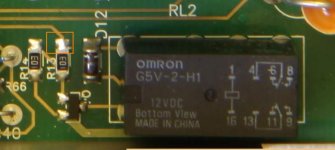
The tjoeb uses an Omron relay. Reviewed it on the picture I already made for the first forum post. So the muting circuit is organised a little different.
It could indeed be wise to avoid "pops", a good suggestion, with tubes don't now. So if it is easy to do why not.
Connections to the Tjoeb dac board are exactly the same as the CD4000 DAC, as the rest of the player is not modified.
The tjoeb uses an Omron relay. Reviewed it on the picture I already made for the first forum post. So the muting circuit is organised a little different.
It could indeed be wise to avoid "pops", a good suggestion, with tubes don't now. So if it is easy to do why not.
Attachments
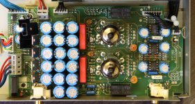
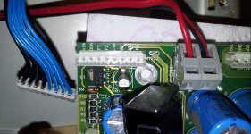
I made a few High res pictures of the inside of the Tjoeb, the circuit board is much more complex and it also uses SMD components.... And it is double layer.
I did not yet make one of the below side of the board, it cannot be easily removed. The wires are very stiff and need to be disconnected.
The pictures you can (I think) save in High res mode, the lines can be clearly seen, also components. Hope we can figure it out.
Regards, HJH
I did not yet make one of the below side of the board, it cannot be easily removed. The wires are very stiff and need to be disconnected.
The pictures you can (I think) save in High res mode, the lines can be clearly seen, also components. Hope we can figure it out.
Regards, HJH
Attachments
It's indeed quite different.
From those pics, I'd think the relay at the top of the board (near the drive) is not switching signal but rather switching the power line going to the drive. It doesn't interest us much.
The output muting relay is probably the bottom one.
PS: outstanding photo work btw.
From those pics, I'd think the relay at the top of the board (near the drive) is not switching signal but rather switching the power line going to the drive. It doesn't interest us much.
The output muting relay is probably the bottom one.
PS: outstanding photo work btw.
Thx, using a Canon EOS 50d from a steady rest.
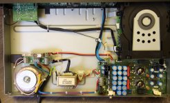
Just loosened the board from the enclosure to be able to take a picture. Not a very nice construction inside the player Marantz made. The circuit board is scratched at two places due to a metal support. Which cannot be removed or cleared from the board during removal.
I think you're conclusion about the relay's is right. I tried to find out by carefully listening.
The one closest to the drive is clicking immediately after the player is turned on, it has a more loud tick. The one at the back in between the connectors has a very soft tick after pressing play and also when the disc is paused.
Hope we are able to find out how it works based on the pictures.
Regards, HJH
Attachments
Allright.
Wrt the "top" relay. It switches the red wires going from the dac board to the relay board near the toroidal transformer. My guess is that it disables the output tube stage when the player is in standby. In which case the best is to keep the front board connected to keep that functionnality. Not a problem anyway since it's not linked to the play commands.
The second relay is our problem... Btw, the way muting works is the same as with the transistors in the original: output is taken to gnd by default (if the relay is powered down). When the relay is powered up, the connection in between output and gnd is opened.
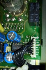
The control transistor is the smd one under the d12 diode. Could you check what happens at the top side of r13 (see pic attached) ? It is probably at 0V when the relay is off, and at 5V or so when it is on. If it is so, we can remove r13 and send a control signal directly at its bottom pad (just a short to 5V or the output of a soft start).
Or we can just remove the relay...
Wrt the "top" relay. It switches the red wires going from the dac board to the relay board near the toroidal transformer. My guess is that it disables the output tube stage when the player is in standby. In which case the best is to keep the front board connected to keep that functionnality. Not a problem anyway since it's not linked to the play commands.
The second relay is our problem... Btw, the way muting works is the same as with the transistors in the original: output is taken to gnd by default (if the relay is powered down). When the relay is powered up, the connection in between output and gnd is opened.
The control transistor is the smd one under the d12 diode. Could you check what happens at the top side of r13 (see pic attached) ? It is probably at 0V when the relay is off, and at 5V or so when it is on. If it is so, we can remove r13 and send a control signal directly at its bottom pad (just a short to 5V or the output of a soft start).
Or we can just remove the relay...
Attachments
Glad to know that you already found how the circuit board is working")
Maybe it is not even needed to have the front board connected, as I refer to what we did with the CD4000 board. This was also on by default, so if I understand correctly the relay will be triggered at power on.
So therefore I was thinking to place a switch in the 220V line, so powering everything off/on. Would this not also work for the Tjoeb board?
(I would think that a stby function is not needed, as when I'm listening its on and afterwards off again.)
Tonight I will measure R13 to measure how it is switching.
So we would then have two options, bypass the relay or adding a soft start. Adding a 5v signal to R13 would if I understand correctly be the same as removing the relay? (or just bypassing it with a wire on the circuit board?)
Thx HJH
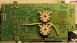
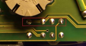
Not sure... it depends on how the muting circuit is made. It's controlled by r10-11-12 and q2-q3. It's worth trying to carefully remove r10 and then see if the tubes power on. If not, you can solder a link under the board, to tie the relay pins together. See attached pic.Maybe it is not even needed to have the front board connected, as I refer to what we did with the CD4000 board. This was also on by default, so if I understand correctly the relay will be triggered at power on.
So therefore I was thinking to place a switch in the 220V line, so powering everything off/on. Would this not also work for the Tjoeb board?
(I would think that a stby function is not needed, as when I'm listening its on and afterwards off again.)
If 5V is the correct signal (to be verified), yes, it's the same as removing the relay. You cannot bypass it, as it ties by default the L/R outputs to ground.Tonight I will measure R13 to measure how it is switching.
So we would then have two options, bypass the relay or adding a soft start. Adding a 5v signal to R13 would if I understand correctly be the same as removing the relay? (or just bypassing it with a wire on the circuit board?)
Attachments
So both relays are working opposite, one connecting to GND and the other Removing the connection to GND
 never worked on SMD. Maybe I should practice on scrap boards....
Thinking the other way around, could this not be tested by just removing the front panel cable and see if the tubes power up? The original CD4000 powers up without the front board. Or is there then a risk for damaging the board. On the other hand, I think I could also easily make a test with connecting the pins with a wire without soldering.
It switches between 0 V at non playing but powered on to 3.9 V when the disc is playing. When pressing pause indeed the signal returns to 0 V.
Kr. HJH
I must admit that I'm not feeling comfortable in removing SMD components...... I can solder wires and normal components, but I'm afraid to damage the board while de-soldering SMD. It's so very small.Not sure... it depends on how the muting circuit is made. It's controlled by r10-11-12 and q2-q3. It's worth trying to carefully remove r10 and then see if the tubes power on. If not, you can solder a link under the board, to tie the relay pins together. See attached pic.
never worked on SMD. Maybe I should practice on scrap boards.... Thinking the other way around, could this not be tested by just removing the front panel cable and see if the tubes power up? The original CD4000 powers up without the front board. Or is there then a risk for damaging the board. On the other hand, I think I could also easily make a test with connecting the pins with a wire without soldering.
Just performed the measurement (used a needle on the small connection...)If 5V is the correct signal (to be verified), yes, it's the same as removing the relay. You cannot bypass it, as it ties by default the L/R outputs to ground.
It switches between 0 V at non playing but powered on to 3.9 V when the disc is playing. When pressing pause indeed the signal returns to 0 V.
Kr. HJH
Last edited:
old computers boards are a great practice ground.I must admit that I'm not feeling comfortable in removing SMD components...... I can solder wires and normal components, but I'm afraid to damage the board while de-soldering SMD. It's so very small.
I don't see how you could damage the board. Try without the front panel cable.Thinking the other way around, could this not be tested by just removing the front panel cable and see if the tubes power up? The original CD4000 powers up without the front board. Or is there then a risk for damaging the board. On the other hand, I think I could also easily make a test with connecting the pins with a wire without soldering.
So all we need is to send 4V to that resistor's place.It switches between 0 V at non playing but powered on to 3.9 V when the disc is playing. When pressing pause indeed the signal returns to 0V.
Could you do the following: the player being powered down, remove the front panel cable and test for continuity from the pins of the front panel cable connector on the dac board to the top of R13 and the bottom of r10 ("top" being the drive side)
Could you do the following: the player being powered down, remove the front panel cable and test for continuity from the pins of the front panel cable connector on the dac board to the top of R13 and the bottom of r10 ("top" being the drive side)
I measured the "Ohms" between the two locations and all the separate pins of the front panel connector.
R10 bottom side:
- 0 Ohm for the pin labelled ST
- The other pins all vary from kOhm to Mohm
R13 top side
- 0 Ohm for the pin labelled KL
- The other pins all vary from kOhm to Mohm
A picture of the connector is below, I found that not all pin labelling was visible in the pictures.
I don't see how you could damage the board. Try without the front panel cable.
Without the front panel connector nothing is happening, not even the main power relay....
I tried to measure between the various pins of the front panel connector (not on the DAC board but on the cable). To find a short or open, but was not able to find. I would expect that PW to GND (DGN) would make sense.
Attachments
ST is thus standby. It controls the top relay, which controls the main power relay and thus the power to the tube stage. From earlier posts, it goes from 5V when the player is put in standby to 0V when powered on.I measured the "Ohms" between the two locations and all the separate pins of the front panel connector.
R10 bottom side:
- 0 Ohm for the pin labelled ST
- The other pins all vary from kOhm to Mohm
R13 top side
- 0 Ohm for the pin labelled KL
- The other pins all vary from kOhm to Mohm
KL is kill, controlling the bottom relay and thus muting. It goes to 5V when playing and 0V when in pause.
If you install a power switch on the 230V input, the easiest is to remove the front panel cable and have a jumper from ST to DGN and a jumper from KL to 5V (all on the same connector). And you're done. You can try without even soldering.
Just made the test with the ST to DGN connection (no Risk, as there is no voltage to be applied).
This is working perfectly, the tubes do power up (both the main relay and tube control relay are clicking)
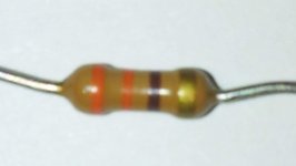
I found a 330 Ohm resistor (attached in picture) that should do the job, a small one, but I think the power handling should be sufficient, or not?
I will make a bridge based on a front panel connector tomorrow, then I can easily solder the resistor in place.
Very happy with this solution.
As a next step I can connect the second player again (to only use the transport) as I did for the first test run with the CD4000, based on this I can test if there are any Pops.
Or is it also very easy now to connect a soft start?
This is working perfectly, the tubes do power up (both the main relay and tube control relay are clicking)
I found a 330 Ohm resistor (attached in picture) that should do the job, a small one, but I think the power handling should be sufficient, or not?
I will make a bridge based on a front panel connector tomorrow, then I can easily solder the resistor in place.
Very happy with this solution.
As a next step I can connect the second player again (to only use the transport) as I did for the first test run with the CD4000, based on this I can test if there are any Pops.
Or is it also very easy now to connect a soft start?
Attachments
That does indeed not look that complicated with only on Transistor, a capacitor and two resistors.
I think I would be able to make this based on a "DIY Circuit board" I'll have one of those boards laying around. See what components I have tomorrow. Think I do not have the transistor.
Are there any specific requirements to the components?
And the connection is easy towards the DAC board.
I think I would be able to make this based on a "DIY Circuit board" I'll have one of those boards laying around. See what components I have tomorrow. Think I do not have the transistor.
Are there any specific requirements to the components?
And the connection is easy towards the DAC board.
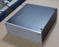
Also found already a nice case on the net to build the complete project into.
Nice one, it looks a bit like the galaxy ones but better. Link ?
Don't hesitate to take it bigger than needed if it's your first big project. Makes things easier.
- Status
- This old topic is closed. If you want to reopen this topic, contact a moderator using the "Report Post" button.
- Home
- Source & Line
- Digital Source
- How to build a Digital input on a Njoe Tjoeb 400 (Marantz CD 4000) cd player