Hello to all,
I would like to modify my cd player, a Njoe Tjoeb 4000, (based on the Marantz CD-4000).
This is in my system for quite some years and I really like the sound of the tube output stage. On the other hand I want to make the change to streaming audio. I made a first step with a Logitech Squeezebox and a separate DAC. It is sounding quite good, but I’m really missing the sound of my Tjoeb.
Therefore my question: Is there a possibility to use the Tjoeb output stage separately? In other words, I’m looking for a possibility to modify the player with a SPDIF or Optical input. For me there is no limitation in modifying the player to a stand-alone DAC (cd drive can be skipped).
Through the internet I tried to find options to do this, unfortunately I’m not skilled in electronics besides doing some basic things. Based on the service manual and some searching I found out that the communication between the Drive and the DAC is by means of an I2S connection.
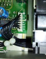
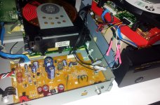
The connections on the circuit board where the Drive is connected are labeled (see also picture 1):
WS - Word clock line
BCK - Serial Bit clock
Data - Serial Data
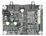
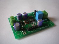
As far as I understand an adapter from SPDIF to I2S should be added. On the internet I found the board as shown on picture 2 and 3.
My question is therefore could this be a good option or should I think in other solutions?
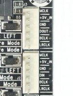
I think the following connections should be made:
WS -> LRCLK
BCK -> BCLK (I do not know the exact difference between MCLK and BCLK, however I think Bit clock)
Data -> DIN
I hope somebody can help or advise.
Thanks in advance!
I would like to modify my cd player, a Njoe Tjoeb 4000, (based on the Marantz CD-4000).
This is in my system for quite some years and I really like the sound of the tube output stage. On the other hand I want to make the change to streaming audio. I made a first step with a Logitech Squeezebox and a separate DAC. It is sounding quite good, but I’m really missing the sound of my Tjoeb.
Therefore my question: Is there a possibility to use the Tjoeb output stage separately? In other words, I’m looking for a possibility to modify the player with a SPDIF or Optical input. For me there is no limitation in modifying the player to a stand-alone DAC (cd drive can be skipped).
Through the internet I tried to find options to do this, unfortunately I’m not skilled in electronics besides doing some basic things. Based on the service manual and some searching I found out that the communication between the Drive and the DAC is by means of an I2S connection.
The connections on the circuit board where the Drive is connected are labeled (see also picture 1):
WS - Word clock line
BCK - Serial Bit clock
Data - Serial Data
As far as I understand an adapter from SPDIF to I2S should be added. On the internet I found the board as shown on picture 2 and 3.
My question is therefore could this be a good option or should I think in other solutions?
I think the following connections should be made:
WS -> LRCLK
BCK -> BCLK (I do not know the exact difference between MCLK and BCLK, however I think Bit clock)
Data -> DIN
I hope somebody can help or advise.
Thanks in advance!
Attachments
The CD4000 is a rebadged philips CD723 with minor changes (better caps, this kind of things). It uses the TDA1545a DAC, which doesn't accept I2S inputs but EIAJ ones. The service manual of the cd723 is floating around the web, if you can't find it, I can mail it to you.
So you'll need either a spdif receiver with an eiaj output or add a I2S to EIAJ converter (schematic can be found on this forum).
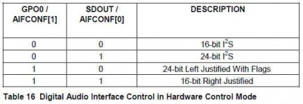
edit: Looking at your board: it uses a wm8804 which can output the required 16bits right justified. SW5 should set the output mode. The board says 16 and 24bit I2S and 24bit left and right justified; in the datasheet, there is no mention of 24 bit right justified mode in hardware mode (see p.19).
I suspect that there is an error and that the last hardware mode of sw5, labeled 24 bit right, is actually 16 bit and what you need. However, I would send an email to the seller to make sure of this.
So you'll need either a spdif receiver with an eiaj output or add a I2S to EIAJ converter (schematic can be found on this forum).
edit: Looking at your board: it uses a wm8804 which can output the required 16bits right justified. SW5 should set the output mode. The board says 16 and 24bit I2S and 24bit left and right justified; in the datasheet, there is no mention of 24 bit right justified mode in hardware mode (see p.19).
I suspect that there is an error and that the last hardware mode of sw5, labeled 24 bit right, is actually 16 bit and what you need. However, I would send an email to the seller to make sure of this.
Last edited:
Hi Ben,
Thanks for your reply, really appreciated.
I found the manual of the Philips, this is indeed the same as for the CD 4000 and has the same pin naming and lay out as inside my Njoe Tjoeb player (picture 1).
I understand from you that this is not the listing of I2S but of EIAJ.
The adapter print is not one I have, but I found it on the net as I was looking for converters. So I was a little on the right way, but with the wrong signal.....
I'm trying to understand (to learn and figure out based on logic)
The EIAJ signal is also called 16 Bit right justified? So therefore I would need an adapter from SPDIF to 16 Bit right justified?
I'm not skilled to make circuit boards of my own, but can make connections between them
Is the board I found maybe an option as the SW 5 mode 24 Bit right would be 16 Bit right justified? This due to the fact that the main chip doesn't have 24 bit?
Which pins should I connect then, as the labels do not resemble.
Or are there other standard board to use?
Thank for your help
Regards,
HJH
It's the board from Sure on ebay, isn't it ? There aren't many other boards for spdif to I2S or EIAJ I'm aware of today, except for the one from twisted pear, which is more expensive.
Yes, EIAJ is another name for 16 bits right justified.
I'm pretty sure (99% certain) that SW5, with the bottom settings, will indeed give you the required format. SW5 appears to be switching the aif[conf0] and aif[conf1] pins.
On the receiver board, you should be able to use the top right connectors. Do the following:
gnd => gnd
dout => data
bclk => bck
lrclk => ws
It is indeed the board of Sure-hifi I found.
I also found the other board from twisted pear you are suggesting. Very strange in my opinion is that neither is mentioning the EIAJ input, but both only mention the I2S format.
I also noticed that both of them mention the 24 bit LRCK. While reviewing the WM8804 manual I noticed that it mentions on page 1: 16-24 bit word length.
Could this explain the naming on the Sure-hifi board.
Furthermore I came across this post at the forum:
http://www.diyaudio.com/forums/digi...8804-transceiver-module-tda1541a-problem.html
It looks like additional switch positions are possible and it can thereby output 16 bit right justified (Pic attached).
But then new pin names are there, some resembling my Tjoeb board. I think it should be then:
BCK -> BCK
SCK -> ? not needed
LRCK -> WS
DOUT -> Data
GND -> GND
Which would be then the better choice? Do both work without additional electronics, the Twisted pear also has a clock input....Also reading some things about input lock and bit rates.
Thx, HJH
Attachments
That's right. SCK (system clock) isn't needed for the tda1545a.
The Twisted Pear doesn't have more options, they're just using a different kind of switches (a more logical one). It also doesn't a clock input but a clock output. You don't need it.
If they don't mention EIAJ, it's because it's a protocol which isn't used much anymore. Almost all DACs commonly used today will accept I2S inputs.
I'd simply get the Sure board. Its functionalities are the same as the TP board and it's cheap enough to experiment.
You're right, found the Sure board for below 20 dollars. The cost are low to try.
Hope that I can adjust it to the 16 bit mode...
I will try first with a standard Marantz 4000 (I already have an old optical abused one), as I do not know if there is some risk for damaging the board of the tjoeb.
Also I need to find out if the AF board of the Tjoeb can work without the connections of the Drive unit. I expect, as the only other connection is DOBM / GND / SHIELD, which is used for the Digital output. And looks separated from the other components.
For sure I will post the result here! This has been very helpful.
Regards,
HJH
Hello Ben,
I've ordered the Sure Hifi circuit board, arrival will take up to a month.
But.......
I'm very curious to continue, therefore I thought let's try already if the system is working by connecting two CD4000's to each other.
My thought was, a CD4000 is outputting the EIAJ signal to the Dac board. So why not connecting the EIAJ output of one player to the other one (Í have two players to test with).
To do this I tapped the DATA, BCK and WS signal of the drive of one player and fed these to the corresponding inputs of the other one.
The player with the disconnected 3 data lines is reacting normal and playing discs.
However the player I fed the signal to is not giving an output on the DAC board .... (all other connections of this player are original). The only thing I can do is to set the "DAC" player also in the Play mode and then I get output but it is completely distorted.
So my conclusion would be that just connecting a new DATA, BCK and WS line would not work (at least if the outputted signal is correct by the other one).
Do you have any idea how to go on? I'm out of idea's as there is somehow some connection that is disturbing. I'm not skilled in reading the board lay-outs.
Hope you have an idea! Thx.
I've ordered the Sure Hifi circuit board, arrival will take up to a month.
But.......
I'm very curious to continue, therefore I thought let's try already if the system is working by connecting two CD4000's to each other.
My thought was, a CD4000 is outputting the EIAJ signal to the Dac board. So why not connecting the EIAJ output of one player to the other one (Í have two players to test with).
To do this I tapped the DATA, BCK and WS signal of the drive of one player and fed these to the corresponding inputs of the other one.
The player with the disconnected 3 data lines is reacting normal and playing discs.
However the player I fed the signal to is not giving an output on the DAC board
.... (all other connections of this player are original). The only thing I can do is to set the "DAC" player also in the Play mode and then I get output but it is completely distorted.So my conclusion would be that just connecting a new DATA, BCK and WS line would not work (at least if the outputted signal is correct by the other one).
Do you have any idea how to go on? I'm out of idea's as there is somehow some connection that is disturbing. I'm not skilled in reading the board lay-outs.
Hope you have an idea! Thx.
All other connections including the GND are connected, for both CD-4000's, I only disconnected and rerouted the DATA, BCK and WS lines.
I did not do it with pefect connections, but leads are not much longer than original, as I placed the two players next to each other.
The signal is completely distorted, not a little.
The photo shows what I did.
I did not do it with pefect connections, but leads are not much longer than original, as I placed the two players next to each other.
The signal is completely distorted, not a little.
The photo shows what I did.
Attachments
Both Cd-4000's are fully connected, I only rerouted the DATA, BCK and WS lines. All GND lines are in original position.
The connections made are not perfectly made, however the length is not much more than original.
The sound outputted is completely distorted and far from normal.
The picture shows what I did.
The connections made are not perfectly made, however the length is not much more than original.
The sound outputted is completely distorted and far from normal.
The picture shows what I did.
Attachments

Electrical signals need a return. You need to connect the ground of the "drive" to the ground of the "dac". You should do so without disconnecting the ground cables inside each player (they serve as return for many things) but by adding a wire from a gnd point in the "drive" to a gnd point in the "dac"
That is indeed very logical and it works! The sound is perfect without distortions even with the not decent wiring.
Just simply connected both casings with a wire.
The only thing that remains is that I need to press play also on the DAC player (both cd drives are spinning).
There is "soft relay" function I suppose, this is upgraded in the Tjoeb by a real Relay (you can hear it clicking).
Next step to try to bypass that....... if possible otherwise my DAC needs a cd drive.
The sound is perfect without distortions even with the not decent wiring.Just simply connected both casings with a wire.
The only thing that remains is that I need to press play also on the DAC player (both cd drives are spinning).
There is "soft relay" function I suppose, this is upgraded in the Tjoeb by a real Relay (you can hear it clicking).
Next step to try to bypass that....... if possible otherwise my DAC needs a cd drive.
Hello Ben,
So far things are going well, I've already learned a lot! Thx.
To make a next step I started with the service manual again to see if I can find the lines that are feeding the mute signal. Based on the manual I was not able to do so, as not all abbreviations of the connections are explained.
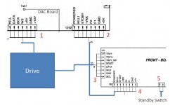
I've listed them in a drawing which I attached to this post
The connector with the EIAJ input is I think not important in this as:
(Connector 1 DAC to Drive)
-Kill -> Kill output, programmable open drain – not needed
-Data -> will be used for EIAJ input board
-BCK -> will be used for EIAJ input board
-WS -> will be used for EIAJ input board
-+ 5V -> Power supply Drive (not needed)
-GND -> will be used for EIAJ input board
-+ 10V -> Power supply Drive (not needed)
The connection between Connector 2 and 4 are I think the important ones. So I started with my measuring device to find out what voltages are on which line (compared to GND). As I would expect that certain voltages will disappear or appear on the pins.
However I could not find any logic...... I measured from power off to power on. I did not find changes in voltages after starting play (what is strange while the muting is disabled with pressing the play button)
This is what I measured:
Connector 2 / 4 (Front board to DAC board)
-Powered -> 4.0 V fixed (both off and on)
-Killi -> ? 0.45 V fixed (both off and on)
-STDBY -> Linked to standby switch 5.0 V off to 0.45 V when turned on
--VKK -> ? -26 V fixed (both off and on)
-F2 -> ? -22.5 V off to -21.5 V powered on
-F1 -> ? -22.5 V off to -21.5 V powered on
-GND
-+5V -> 5 V fixed (Power supply of board)
Am I missing the logic here? are the signals fed also digital lines?
Regards, HJH
So far things are going well, I've already learned a lot! Thx.
To make a next step I started with the service manual again to see if I can find the lines that are feeding the mute signal. Based on the manual I was not able to do so, as not all abbreviations of the connections are explained.
I've listed them in a drawing which I attached to this post
The connector with the EIAJ input is I think not important in this as:
(Connector 1 DAC to Drive)
-Kill -> Kill output, programmable open drain – not needed
-Data -> will be used for EIAJ input board
-BCK -> will be used for EIAJ input board
-WS -> will be used for EIAJ input board
-+ 5V -> Power supply Drive (not needed)
-GND -> will be used for EIAJ input board
-+ 10V -> Power supply Drive (not needed)
The connection between Connector 2 and 4 are I think the important ones. So I started with my measuring device to find out what voltages are on which line (compared to GND). As I would expect that certain voltages will disappear or appear on the pins.
However I could not find any logic...... I measured from power off to power on. I did not find changes in voltages after starting play (what is strange while the muting is disabled with pressing the play button)
This is what I measured:
Connector 2 / 4 (Front board to DAC board)
-Powered -> 4.0 V fixed (both off and on)
-Killi -> ? 0.45 V fixed (both off and on)
-STDBY -> Linked to standby switch 5.0 V off to 0.45 V when turned on
--VKK -> ? -26 V fixed (both off and on)
-F2 -> ? -22.5 V off to -21.5 V powered on
-F1 -> ? -22.5 V off to -21.5 V powered on
-GND
-+5V -> 5 V fixed (Power supply of board)
Am I missing the logic here? are the signals fed also digital lines?
Regards, HJH
Attachments
Just did the measurement there, this voltage is indeed changing. While the player is in stop or pause mode there is 0.25 V on this pin. During playing there is 4.75 V on the pin.
Now I understand what you mean by easy
Is it then so easy to just bridge the +5V of the connector to Kill or should it be the exact measured voltage?
On the 5V pin I measure 5.4 V
HJH
Now I understand what you mean by easy
Is it then so easy to just bridge the +5V of the connector to Kill or should it be the exact measured voltage?
On the 5V pin I measure 5.4 V
HJH
Last edited:
To be complete: muting is controlled by KILLI (on the connector going from dac board to the front board) and by KILL (on the connector going from dac to drive). Both signals have to change to allow the output to be active.
- To deal with KILLI: disconnect completely the front board from the dac board. Remove the 6500 1N4148 diode on the dac board. That's it.
- To deal with KILL: remove the resistor labelled 3534 on the dac board. That's it.
- To deal with KILLI: disconnect completely the front board from the dac board. Remove the 6500 1N4148 diode on the dac board. That's it.
- To deal with KILL: remove the resistor labelled 3534 on the dac board. That's it.
Ok, that's clear, I will locate them and remove them. Will do that in a few moments.
The only thing is that the power switch is then also disconnected.....(it's directly linked to the front board.)
Am I right that the board is then by default on, (based on my measurements)
The only thing is that the power switch is then also disconnected.....(it's directly linked to the front board.)
Am I right that the board is then by default on, (based on my measurements)
Hello Ben,
perfect solution! I've just tried it and noticed that the power button is non functional, so everything is removed and only the DAC board is playing.
Only one for me difficult part remains in modifying the Tjoeb. How to locate the resistor and diode on that board (the board is using a relay). I do not have a diagram of it.
Is it something you would be able to see based on detailed pictures? Both from the top and the bottom?
Really happy that the solution has been defined. Now to transfer to the Tjoeb.
Regards, HJH
P.s. / FYI: I also found another very nice small circuit board dedicated for 16 bit Rjust. from TekDevice
perfect solution!
I've just tried it and noticed that the power button is non functional, so everything is removed and only the DAC board is playing.Only one for me difficult part remains in modifying the Tjoeb. How to locate the resistor and diode on that board (the board is using a relay). I do not have a diagram of it.
Is it something you would be able to see based on detailed pictures? Both from the top and the bottom?
Really happy that the solution has been defined. Now to transfer to the Tjoeb.
Regards, HJH
P.s. / FYI: I also found another very nice small circuit board dedicated for 16 bit Rjust. from TekDevice
Attachments
- Status
- This old topic is closed. If you want to reopen this topic, contact a moderator using the "Report Post" button.
- Home
- Source & Line
- Digital Source
- How to build a Digital input on a Njoe Tjoeb 400 (Marantz CD 4000) cd player