Happy New Year Guys,
I am planning to upgrade my Wolfson WM8741 DAC (voltage output) with output transformer bypassing the opamps as below:
WM8741 DAC balanced v-output --> primary of transformer --> secondary of transformer (single ended) --> 25K stepper attenuator --> preamp (jfet 2SK170 based)
Given the wolfson dac is voltage output type, I guess 600:600 transformer may not be the good choice.
Edcorusa is offering transformers with different primary higher than 600:
http://www.edcorusa.com/c/11/openframematchers
XSM2.4K/600
XSM10K/600
XSM10K/10K
Can you please recommend an EDCOR matching transformer for my setup?
thanks alot
Jack
Last edited:
Hi Jack,
I am currently considering a similar approach to interface my Linn Sneaky DAC Output to my balanced F5X amplifier.
For the transformer I am not convinced that the encordusa are a good choice though.
For instance the WSM600/600 is specified with 0.05% THD @ 1kHz.
Besides this value isn´t impressive at all no test conditions such as source impendance or signal amplitude is given.
I am considering a Jensen Line Level Output Transformer
http://www.jensen-transformers.com/datashts/11bmcf.pdf
Why Jensen? Among all potential transformer manufacturers I have found so far they provide the clearest spec sheet and what is in looks quite promising.
And yes, they are not cheep but you know what you will get.
Markus
Hi Markus,
Thanks for your reply.
As my DAC output is about 1.2Komh, so I guess the 10:10k transformer may fit my system, in stead of the 11bmch which is 600:600.
I have purchased a pair of Jensen JT-11P-1 (10k:10k). I connected the Jensen from my DAC chipset output (balanced) to my single-ended Pre-amp without any capacitors involved.
The sound was completely moved up to a higher level, even my wife in other room (8 meters from my living room) could hear the difference. Now I heard lots of details I missed in the past, the bandwidth was wider, the sound stage was improved with 3D...
I did roll back to my original setup and let my friends to compare, they all agreed that the Jensen is the magic little box")
However I can't be 100% sure that the 600:600 11BMC won't do the same job as 11P-1 (10k:10k), I really hope you have a chance to compare them both and let us know your view.
Again, thank you so much for your advice.
Jack
Thanks for your reply.
As my DAC output is about 1.2Komh, so I guess the 10:10k transformer may fit my system, in stead of the 11bmch which is 600:600.
I have purchased a pair of Jensen JT-11P-1 (10k:10k). I connected the Jensen from my DAC chipset output (balanced) to my single-ended Pre-amp without any capacitors involved.
The sound was completely moved up to a higher level, even my wife in other room (8 meters from my living room) could hear the difference. Now I heard lots of details I missed in the past, the bandwidth was wider, the sound stage was improved with 3D...
I did roll back to my original setup and let my friends to compare, they all agreed that the Jensen is the magic little box
However I can't be 100% sure that the 600:600 11BMC won't do the same job as 11P-1 (10k:10k), I really hope you have a chance to compare them both and let us know your view.
Again, thank you so much for your advice.
Jack
Hi Jack,
by coincidence I came across this thead again. I am sorry that I missed your replay that time because of some other urgencies I had to take care of. Anyhow, I am glad to read that you were happy with my suggestion. I am revisting my DAC transformer project now.
May I ask if you are still happy with the configuration you have started with or if you have made modificaitions to it meanwhile that you would recommend or experiences that you could share?
All the best
Markus
All, thanks for your response.
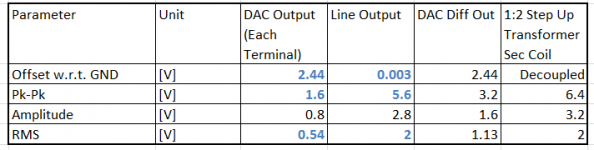
I just did some measurements to find out the signal levels at the DAC output of the Wolfson WM8740 of my Linn Sneaky DS. The amplitudes are listed below. So if I would use a step - up transformer with a turns ratio of 1:2, which means a voltage gain of two, then I could pick up GND-decoupled balanced signals at line level standard amplitude (2Vrms) at the secondary port of the transformer. That´s good, this means no preamplifier would be needed and I could go ahead with a passive pre-amp, i.e. an steppled (shunt?) attenuator. Unfortunately there are not much choices of 1:2 step-up line output transformers. The only two I found at Jensen are the JT-123-BMCF and the JT-123-BLCF. The down side of these transformers is however their rather low input impedance of 150Ohms which is not compatible with the DAC output specification that requires a load resistance at the output higher then 0.6-1kOhm.
Maybe I should consider a JFET buffer in between the DAC output and the transformer.
Markus
Attachments
All, thanks for your response.
I just did some measurements to find out the signal levels at the DAC output of the Wolfson WM8740 of my Linn Sneaky DS. The amplitudes are listed below. So if I would use a step - up transformer with a turns ratio of 1:2, which means a voltage gain of two, then I could pick up GND-decoupled balanced signals at line level standard amplitude (2Vrms) at the secondary port of the transformer. That´s good, this means no preamplifier would be needed and I could go ahead with a passive pre-amp, i.e. an steppled (shunt?) attenuator. Unfortunately there are not much choices of 1:2 step-up line output transformers. The only two I found at Jensen are the JT-123-BMCF and the JT-123-BLCF. The down side of these transformers is however their rather low input impedance of 150Ohms which is not compatible with the DAC output specification that requires a load resistance at the output higher then 0.6-1kOhm.
Maybe I should consider a JFET buffer in between the DAC output and the transformer.
Markus
Good luck on your project.
1) the impedance (or load required by the DAC) is not the number on the transformer. The impedance that the DAC "sees" is the impedance of the load as reflected by the transformer. If the transformer steps up the voltage by 2 then the load reflected back to the DAC will decrease by a factor of four (2 squared).
An alternative supplier of step up transformers for this application is Edcor (in the USA). The WSM series. They are not as good as the Jensen, but they are considerably less expensive (you can pay quite bit for transformers).
When choosing a transformer, please keep in mind the unit's inductance. If it is too low then you will create a high pass filter (and you will lose your lows). It is a function the inductance and the R of the Source (mostly) and the R of the Load (somewhat).
Hi WithTarragon,
many thanks for your remarks. I should have studied the datasheet more carefully before drawing a conclusion. Of course you are right, the 150Ohms is the mirrored back 600Ohms load resistor across the secondary terminals used in the measurement.
And you are right, the primary inductance is important, but I cannot find it in the datasheet. I will try to extract this from the information given in the datasheet and establish a small signal transformer model as a basis for my design. Then I will also see what information is missing.
On the Edcor transformers, thanks for the hint, I will check out what thy offer.
All the best
Markus
Finally I ordered two samples of the Jensen JT-123-BMCF and I run some impedance measurements. I found out that these transformers are not suitable for being directly connected to DAC since they need a very low impedance signal source that is also capable to drive a low impedance load (170 Ohms or less depending on the load on the secondary side). The latter is certainly not the case for WM8740 DAC which according to the datasheet could only drive loads with a impedance higher than 600Ohms.
I am convinced that the JT-11P-1 (10k : 10k) Jack has ordered and was happy with is the much better choice for direct DAC to Amp connection, for now understood reasons.
Regards
Markus
I am convinced that the JT-11P-1 (10k : 10k) Jack has ordered and was happy with is the much better choice for direct DAC to Amp connection, for now understood reasons.
Regards
Markus
I had a brief look into the Cimemag CMLI 15-15B datasheet. It seems to me that this transformer is quite comparable with the JT-11P-1 transformer. I do not see an obvois problem with operating this transformer on a WM8740 DAC output. The coil resistance of each coil is already 1.5k, so the input impedance will never drop below 3k (within the transformer passband) even if the terminals of the secondary coils are shorted. Be prepared however, that also the output impedance of the transformer will never go below 3k. So even with a 10k load resistance you will ge a voltage drop by factor of 10k/(10k+3k) = 0.77. So you have to make sure that the sink impedance will not go far below 10k.
Do you have some experience with this transformer alreaady?
Markus
Do you have some experience with this transformer alreaady?
Markus
Can somebody post a schematic of connection of the transformer to the DAC? I am personally confused with the 2 kohm resistive load requirement "to the midrail or AC coupled". If my secondary sees 33 kohm, and I use 1:1 transformer, do I need any other resistor across secundary, except for sound tuning?
Well the statement "to the midrail or AC coupled" in the WM8740 datasheet is a bit confusing, I would even say it is a lousy definition. What is meant here, at least what I interpret is the following. The DAC output terminals have an offset w.r.t. GND, in the case of my Linn Sneaky this offset is 2.44V and this is the voltage which is referred to as midrail. This rail does not physically exist, there is no midrail pin at the DAC. But if you would generate yourself a midrail with 2.44V, then the minimum resistance from DAC output terminal to that rail would be the specified minimum load resistance value you find in the datahseet, which is my case 600Ohm. "or AC coupled" means that also AC coupled networks, you will find some in the OpAmp filter circuits further down in the DAC datasheet should have an impedance higher then 600 Ohms. So long story short, no load resistance lower then the specified values and resistive coupling a voltage other than midrail.
As for hooking up the transformer to the DAC. Just connect the primary coil terminal to the DAC differential output pins. Your 33kOhms load across the secondary coil will be mirrored 1:1 to the primary side. I am not sure what you mean by "sound tuning" but as long as your network attached to the secondary side has an input impedance higher then the minimum specified value life is good ( at least for the DAC)
Markus
What I meant by sound tuning was determining optimal load for the DAC. As many members of the forum reported, significant changes of sound can be achieved by varying the load of the DAC. Obviously we should not go below recommended value in the data sheet. I was therefore considering to put an potentiometer in parallel with the amp and experiment with different values. For safety I can put 2k2 resistor in series with the pot not to go below recommended minimum.
As for sound tuing. Well you could try to play around with resistances and create a new audio myth as many others in this forum do. Let me recommend to do measurements instead to gain an understanding of what is going on. I did run frequency response measusurements with my JT-123-BMCF transformer to get the input impedance and the primary to secondary voltage gain for various loads resistances. As long as the source output impedance is low ( I assume less then 1 Ohm for the DAC voltage output) the load resistance has very little effect on the voltage gain frequency response. So how would you do sound tuning by means of load resistance here? The picture will change of corse if the source out impedance is is going up. This no-ideal situation will make the transformer voltage gain very dependent on the load resistance as you could see on on the right side plot where the gains for a 50 Ohms source resistance (solid lines) is compared with the gains of a source with 0 Ohms output resistance (dotted lines).
Markus
Markus
Attachments
I cannot say that I understand the graphs you have posted but I understand the message - with voltage output DAC with very low output impedance there is little if anything possible to change with the change of the load resistance. To be quite honest, most of the posts related to tuning the load resistance I read in posts regarding the ES9018, that has output impedance about 200 Ohm and can even work as current source when connected to virtual ground.
Cheers,
Boris
Cheers,
Boris
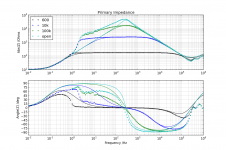
What I tried to show with the data-plots is the following
First plot: The measured frequency response of the impedance across the terminals of the primary coil for different load resistors (600R, 10k, 100k and inf.=open) across the terminals of the secondary coil. The transformer was operated in a 1:2 step up configuration. So the load resistor is mirrored back from the secondary coil to the primary coil by a factor of 1/2^2 = 1/4. (The dotted lines represent the measurement points, solid lines represent related response of the derived lumped model)
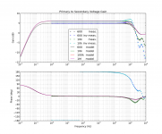
Second plot: The measured primary to secondary voltage gain frequency responses for different load resistances with a source with 0 Ohms output impedance.
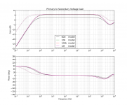
Third plot: The modeled primary to secondary voltage gain frequency responses for different load resistances for the case of a 50 Ohms source output impedance ( solid lines) is compared with the gains in the case of an ideal voltage source, meaning zero output impedance. What you see that te bandwidth is narrowed down significantly as the source impedance increases.
Regarding the idea of combining a transformer with the Sabre DAC. Honestly I do not understand what the transformer should do for you. An ideal transformer transforms voltages to voltages and currents to currents according to the turns ratio. And accordingly it mirrors impedances from primary to secondary and vice versa by the turns ration squared. So a transformer will never work as an I-V converter for you. Furthermore, due to the coil resistances (10Ohms in the case of the JT-123-BMCF) it could never serve as a low resistance virtual GND.
Greetings
Markus
First plot: The measured frequency response of the impedance across the terminals of the primary coil for different load resistors (600R, 10k, 100k and inf.=open) across the terminals of the secondary coil. The transformer was operated in a 1:2 step up configuration. So the load resistor is mirrored back from the secondary coil to the primary coil by a factor of 1/2^2 = 1/4. (The dotted lines represent the measurement points, solid lines represent related response of the derived lumped model)
Second plot: The measured primary to secondary voltage gain frequency responses for different load resistances with a source with 0 Ohms output impedance.
Third plot: The modeled primary to secondary voltage gain frequency responses for different load resistances for the case of a 50 Ohms source output impedance ( solid lines) is compared with the gains in the case of an ideal voltage source, meaning zero output impedance. What you see that te bandwidth is narrowed down significantly as the source impedance increases.
Regarding the idea of combining a transformer with the Sabre DAC. Honestly I do not understand what the transformer should do for you. An ideal transformer transforms voltages to voltages and currents to currents according to the turns ratio. And accordingly it mirrors impedances from primary to secondary and vice versa by the turns ration squared. So a transformer will never work as an I-V converter for you. Furthermore, due to the coil resistances (10Ohms in the case of the JT-123-BMCF) it could never serve as a low resistance virtual GND.
Greetings
Markus
- Status
- This old topic is closed. If you want to reopen this topic, contact a moderator using the "Report Post" button.
- Home
- Source & Line
- Digital Source
- Output transformer for Wolfson WM8741 DAC (voltage output)