I have been trying to build an ECL oscillator similar do the circuits described in the IQD crystal data book, by Winser and by Unruh (the latter two articles were on the ACG pages when they were still in service - what happenend to them?).
Basically, in this circuit the crystal is used in series resonant mode, it is connected from the non-inverting output to the non-inverting input, which in turn has a 15R load to AC ground. The rest is just for getting the DC setpoints right. The input is shorted to ground by the 15 R resistor for all frequencies except the series resonant mode where the crystal has nothing but its real impedance, which is around 10-20 R for HC-49 case devices.
As the 10216 ECL line receiver is not easily available, I used the single gate. 10H16 PECL line receiver. Apart from being faster (0.5 ns prop delay) which wouldn't hurt in this application, the chip is just the same.
Initially, the circuit would sometimes not start up, sometimes start up at the desired frequency, sometime start up in a spurious oscillation aroung 300-600 MHz. I tried various crystals, load resistors beween 10 and 39 R, loutput pull - downs between 100 and 200 R. No change.
The I found that the returns from the input and output loads had different vias to the ground plane just half an inch apart. I provided another wire bridge. The spurious oscillations were gone, but so was the fundamental oscillation. Even injecting a square wave signal couldn't humor the circuit into oscillation. Any ideas?
Frustated,
Eric
ECL oscillator
Hi Eric,
First a important question : what is the frequency of the crystal you are using?
From about 20 Mhz and up crystals operate in the third overtone mode and from about 80 MHz in the fifth overtone mode. It also depends on the manufacturer. Especially the overtone crystals are very temperamental to put it mildly.
Personally I don't have experience with these ECL oscillators, but collected some 10116's in the shoebox.")
Hi Eric,
First a important question : what is the frequency of the crystal you are using?
From about 20 Mhz and up crystals operate in the third overtone mode and from about 80 MHz in the fifth overtone mode. It also depends on the manufacturer. Especially the overtone crystals are very temperamental to put it mildly.
Personally I don't have experience with these ECL oscillators, but collected some 10116's in the shoebox.
Hi Elso,
those were all fundamental mode crystals, I tried various specimen from 12 to 20 MHz. All worked nicely when inserted in the classic 74HCU04 circuit.
I followed your link to the Jung-like regulators. I think I have seen something similar in some AD app note, only that they took some great care to avoid oscillation.
Regards,
Eric
found the solution
Redid the circuit on a spare PCB, not having soldered in the ECL-to-TTL translator helped, too.
1) I removed the two low pass filters that are used in the IQD, Winser and Unruh circuits to derive the DC setpoint. Instead, I feed the inverting input directly from the V_BB pin, with a 100 nF to ground. That is the nice thing about using a line receiver gate, it actually provides the DC reference. Not sure that this is critical, but it sure reducec component count by two resistors and two capacitors.
2) Soldered the load resistor across from non-inverting to inverting input instead to ground. Should be the same, as the inverting input is also grounded, but sure removes a couple of mm worth of copper which will have some impedance.
After these alterations, the circuit worked fine with one of the more benign crystals, even with a 39 R input load resistor.
Having implemented these changes into the final board (which has the translator soldered in), it worked most of the time, but sometimes I got the spurios oscillation (150 to 400 MHz). Lowering the input load to 10 R helped. On start-up, the spurious oscillation lingered, but it would always give way to the crystal fundamental mode after a second.
I put in the 16.9344 crystal salvaged from a Sony player. Now I could trigger the fundamental mode only when I played with the scope probe. I lowered the load to 8.7 R - fundamental mode kicked in somewhat more easily. This gave me the clue: the circuit still had too much gain aroung 150 MHz. A 100 pF in parallel to the input load rolled of gain by 3 dB at 150 MHz. Now the fundamental is there right from the start
Will post the circuit some day when I get to draw it...
Eric
ECL oscillator
Hi Eric,
Glad to hear it is working now.
Don't use the three leaded crystal from the Sony. It is more like a crystal <B>filter</B> Use a "normal" 16.9344 Mhz crystal.
The tendency of your circuit to oscillate at a much higher frequency reminds me of my early attemps to build a oscillator with the LT1016. Too much drive on the crystal.
The KWAK-CLOCK uses gentle, minimal drive to the crystal resulting in much lower jitter and absolutely no spurious oscillations.
three leads
Dear Elso,
in the three leaded crystals provided by IQD/C-MAC, the third lead is simply the case. This saves you having to solder a wire from the ground plane to the case.
There are three leaded little blue things, too. These are ceramic resonators which have much higher internal damping than crystals. The Q of a resonator is on the order of 1000 where a 16 MHz crytal in the large HC49 case will have about 80000. The center lead is also ground, but in addition there are two lag capacitors to each active pin of the resonator.
My ECL circuit uses the crystal in series resonance where its impedance becomes equal to its series resistance which is typically about 10-15 R. You want to provide a low impedance drive and load to keep the Q of the circuit. The drive into the crystal is about 900 mV with a square wave. On the load side, I get a beautiful 400 mV sine. In first order approximation, I am dissipating about 20 mW in the crystal. This may be to much as most crystals are specified at 1- 5 mW. That is why I am trying to find the article on the Winser clock implemented into a TEAC that was on the ACG pages. The author (Werdin?) did line out how to measure and calculate the crystal drive. If I don't find it, I'll have to do the math myself...
Your Quak clock appears to use parallel resonance. Here the resonator impedance becomes infinite. To preserve Q, you want to load the circuit as little as possible. The 10 M resistor looks fine. However, I am a little puzzled whether the 1 k source resistor won't introduce too much damping. What do you think? Also, what does the 10 pF in series with the crystal do? I assume it corrects the crystal frequency but this is really a circuit you would expect to find in a series resonant circuit.
What do you think?
Regards,
Eric
Hi Eric,
Found in my archives the paper by Wedin. As I only got a paper version, I copy the whole paragraph.
Here we go
"The current through the crystal (and the load resistor) is the square root of the crystal's maximum permissible power dissipation divided by its internal series resistance, I=Pxs/Rxs. With values inserted, 0.5mW and 13 ohms, we get 6.2 mA. The voltage drop accross the crystal is the square root of the maximum permissible power dissipation multiplied by the crystal's internal series resistance, U=Pxs*Rxs. With values inserted we get 0.081 Vrms. The ECL-receiver (0.8Vpp or 0.28Vrms), Url=Uecl-Uxs. With values inserted we get 0.2 Vrms. Finally we get the value of the load resistance as the voltage drop of the load resistor divided by the current through it, Rl=Url/I. With values inserted we get 32 Ohms."
N.B. : 0.5 mW is the value of the max dissipation of Wedin's crystal, and 13 Ohms is the internal series resistance he had get, taking two thirds of the manufacturer's value (20 Ohms)
If you're interested, drop me an e-mail with your address, and I'll send a paper copy of the whole paper.
Elso,
I'm about to test your clock with both the fast comparator and the mosfet we talked about. I have to finish PCB design, but in a week or two, I should have some results to post here.
Cheers
thanxxx!
Hi Francois,
thanks for copying that paragraph. That will certainly help me. I think I still have a paper copy, but it is still in one of countless not yet unpacked boxes (moved two months ago).
From the literature I have found on oscillators, I guess the subject of how to make a very high Q oscillator has not been delved into. Some authors appear even to be confused whether they use parallel or series resonance.
Where is Limoges? I think I have been there.
Greetings,
Eric
did the math
Well, I did a few quick calculations. I am dissipating about 2 mW, the crystal is presumably specified for 1 mW.
However, I am not sure that that part is entirely correct. First of all, it assumes everything to be in phase. I guess, in series resonance this is a pretty accurate guess. I will check, though...
However, I am not happy with the treatment of the dissipation. After all, the crystal is driven by a square wave (at least with a fast ECL unit), and it outputs a sine. I thought he commented on that, I think. Do you recall what the article was called?
I am beginning to think about some improvements. For example, the resistive load might be replaced by an LC series resonant circuit. Also, the ECL line receiver could be built in a discrete circuit. This way, it would be possible to limit the drive and still maintain a low impedance load.
Greetings,
Eric
If it can help...
Hi back,
I dunno if you already know it, but a lot of interesting informations can be found at
http://www.telequarz.de/info/info_q.html
(this is the direct link, but can be reached in a regular way to see all other docs : http://www.telequarz.de/index_e.html )
And, lucky guy, there's a nice book on quartz and oscillators, and IT'S IN GERMAN !!
Most instersting chapters (IMHO, and if I may guess from my poooooooor german) are chapter 2 (mostly theoretical) and chapter 6, with oscillators analysis.
Chapter 2 is summed up in the first pdf than can be downloaded.
Wedin's article is called "Re-clocking TEAC VRDS-T1 and TEAC VRDS-7"
And, oh, Limoges is 300km south from Paris, near the center of France
Hi back,
I dunno if you already know it, but a lot of interesting informations can be found at
http://www.telequarz.de/info/info_q.html
(this is the direct link, but can be reached in a regular way to see all other docs : http://www.telequarz.de/index_e.html )
And, lucky guy, there's a nice book on quartz and oscillators, and IT'S IN GERMAN
!! Most instersting chapters (IMHO, and if I may guess from my poooooooor german) are chapter 2 (mostly theoretical) and chapter 6, with oscillators analysis.
Chapter 2 is summed up in the first pdf than can be downloaded.
Wedin's article is called "Re-clocking TEAC VRDS-T1 and TEAC VRDS-7"
And, oh, Limoges is 300km south from Paris, near the center of France
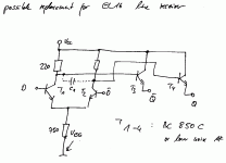
Dual gate MOSFET in place of comparator in the KWAK-CLOCK
Hi Francois,
Just tried the BF980 Dual gate MOSFET in place of the AD8561 comparator in the KWAK-CLOCK as in the Elektor circuit kindly provided by you.
The good news is it works!; the bad news is that the <B>magic is gone!</B>. Sonically it is a big step backwards. I suspect the MOSFET produces a clipped sinewave at best and not a square wave as desired.
Gone is the incredible depth of the soundstage and the fine bass. Also found a lack of definition in the sound with the MOSFET.
three leaded Sony Crystal
Hi Eric,
I only wanted to warn you as the three leaded Sony crystal produces a much worse sound than the two leaded type they also use in some of there players. Notably the types with R2R ladder type dac's. I am aware that the third leg is connected to ground. Just <B><I>practical</B></I> experience sharing with you.
As for the component value's of the KWAK-CLOCK; these are optimised by ear and a close look at other circuits.
I also watched for startup without problems. The KWAK-CLOCK circuit accomodates a wide range of crystal frequencies from 8 to 20 MHz. I have tried a active current source in place of the source resistor. It was NOT a improvement. I have tried <B>MANY</B> other things, including bipolar transistors and other FET's, too much to elaborate on here.
Elso,
Good and bad news
Some care must be taken with the dual gate mosfet. First, there MUST be a capacitor (1nF or less) between your oscillator and G1 of the mosfet (I don't have your schametics handy, and I don't remember you have one). Secondly, you will probably be better with a drain resistance of 560 or 470 Ohms for the mosfet. And last, I'm not sure that G2 should be tight to 5V. I was planning to use a 100K trimpot to vary G2 potential. This voltage acts as a kind of commutation threshold for the mosfet. I will compare with yours using a 300MHz scope, maybe it will help to understand. Last of the last, I will check the BF980 datasheet and compare it with the BF998's, which I'm planning to use, to see if their caracteristics are comparable.
Eric,
Thanxxxx for your translation proposal. I'll check the interesting points for me, and ring you back
Q
Elso,
I am beginning to see what your circuit which is basically a Colpitts oscillator does. The crystal is used at slightly above the series resonant frequence where it appears inductive. This inductance will form a parallel resonant circuit with the series combination of the 39 and 68 pF capacitors. The crystal appears inductive only for a narrow frequency region, and somewhere in this region the parallel circuit has its resonance, i.e. its impedance will become high, at roughly 4x times ESR of the crystal. Hencce, at this frequency the input short is almost removed.
The transistor source drives this parallel circuit through the capacitive tap provided by the two capacitors. The drive impedance should be as low as possible, and it is derived from the dynamic output impedance of the transistor in parallel with the source resistor. That is why a current source did not do any good.
I don't know what the operating point (is it a JFET or MOSFET?) is in your case but I assume the dynamic output impedance to be on the order of 200-400 R. This is a fairly low output impedance but I think there is room for improvement. You could buffer the source by a NPN emitter follower and feed the emitter voltage back to the parallel resonant circuit. You would have the same AC output and drive voltage (with a 0.6 V DC offset) but you can easily achieve <5 R output impedance by running the NPN at 5 mA.
The 10 M gate bias resistor should not really degrade Q compared to the < 500 R drive impedance. However, I am not quite sure whether it is really in AC parallel with the drive. If it is not, it might be degrading Q. You might want to use an AC bootstrap circuit to increase the impedance at the gate and listen...
Eric
low phase noise circuits
Francois,
it is actually chapter 7 that deals with phase noise. Unfortunately, all the greek symbols are missing, so it is a bit difficult to read. Most of it is about definitions and measurements of noise.
But there are also some guidelines for a low phase noise circuit (as in any cookbook):
- don't degrade Q (naturally)
- run the quartz at a high dissipation (this will degrade long term frequency stability, but that does not bother us...)
- if using a bipolar transistor, choose a low frequency, low noise type with high DC current gain h_FE and low base resistance (reason given: phase noise is at several Hz around the fundamental, and here the LF noise performance is more important than the HF noise performance)
- choose a transit frequency of about 5x the crystal frequency (this I don't understand, because then the AC current gain will be roughly 5 and hence there will be a significant load on the crystal, roughly 5x R_E for an emitter follower)
- PNPs are less noisy than NPNs (one never realy is finished with learning...)
- JFETS are less noise than bipolar transistors
- MOSFETs are noisier than bipolars
- GaAs-Transistors are low noise at HF but have very high noise at LF
- make sure the amplifier remains in its linear region (usually amplifier non-linearities are used to limit the impedance but this will cause side band noise)
- implement the amplitude control seperately from the HF amplification
- overtone crystals usually have higher Q when implemented into a real circuit
I guess I will try to compute the effective Q of various circuits (Colpitts, Pierce, ECL) to determine when a resistance is desirable and when it is not....
Eric
To capslock
The creek symbol problem has to be a problem with your acrobat reader. I can see these just fine. I'm using Acrobat Reader 4.05c I tried version 5 for a while but it seemed to have many problems I don't have with older version (schematics getting fuzzy when zooming etc.) So if you can try the version 4...
Ergo
Eric,
Thanks for this insightful summary ! All the points you mention confirm what I have read before. Concerning the transistor's transition frequency, it puzzles me too. Take a look at http://sss-mag.com/pdf/lonsosc.pdf , they have a different approach Or maybe they don't speak of the same thing. The more I try to learn, the less I know
Cheers
Thanks for this insightful summary ! All the points you mention confirm what I have read before. Concerning the transistor's transition frequency, it puzzles me too. Take a look at http://sss-mag.com/pdf/lonsosc.pdf , they have a different approach
Or maybe they don't speak of the same thing. The more I try to learn, the less I know Cheers
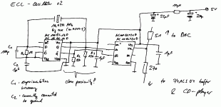
ECL schematic
As promised a long time ago, my oscillator circuit!
constructional notes:
- The crystal feeds the output back to the input, but this signal gets shunted by R1 and C1. On resonance, the impedance of the crystal is minimal. Drive to the crystal has very low impedance, but the shunt impedance is also low. So I am not sure about the claims repeated throughout the literature that this or similar circuits actually have a very high Q. How does one compute Q here?
- Connecting the shunt across the inputs was the only way to make the circuit work, and it is probably the best way, too.
- The circuit worked fine with R1 = 9 R, however, I was not sure if I wasn't overdriving the crystal. Doing the math for the power dissipation isn't trivial because the drive voltage is not a sinusoidal as suggested by the IQD app note or Wedin's article. Also, without a model for the particular crystal, one can never be sure where exactly (slightly of series resonance) it really resonates.
High drive is good for jitter performance but will degrade long term stability. Also, I am not sure that a severely overdriven crystal will still give good jitter performance.
- Make sure not to use a crystal in a HC-49S or similar small case. The crystals in the big cases can stand higher drive and they have lower series resistance, i.e. higher inherent Q.
- C1 was necessary to prevent the circuit from starting up at about 700 MHz occasionally. Required value depends on layout. Make sure that 1/(2*PI*f_crystal) is still at least 5x larger than R1.
- C2 is still connected to ground in my prototype. The next PCB will have it connected to V_CC which is the internal reference node of the ECL line receiver.
Next installment: possible improvements
Comments? Questions?
The attached file is GIF even if the extension is zip. Why is this forum so picky about extensions?
Greetings,
Eric
Attachments
possible improvement: discrete ECL
This attachment shows a discrete version of the ECL line receiver. D-bar should be connected to V_BB which should be -1.3V relative to V_CC and may be generated by a simple divider.
Using AF low noise transistors should result in lower low frequency jitter. I have not yet built the circuit, so I am not sure if the circuit is slow enough so the output will be sinusoidal. One could include C1 to smear the edges. This should not degrade the output impedance which depends mainly on the current of the emitter followers.
One basic problem remains. While the differential amp is essentially a low noise and reasonably linear amplifier, some nonlinearity is needed to keep the oscillation amplitude in check. The collector resistors are chosen at 220 R to limit the swing before any of the transistors goes into saturation (that was the original idea behind ECL). In our case, it will also limit the drive voltage to the crystal, so the drive to the crytal can never be spectrally pure. C1 may filter out some of the harmonics, but the rest is left to the crystal to handle.
One could make the diff amp even more linear by using a higher supply voltage and emitter degeneration resistors. But when compression sets in later, the circuit will automatically settle at a higher oscillation amplitude. Therefore, some sort of AGC (automatic gain control) is needed. One could replace the 750 R tail resistor by a voltage controlled current source. My problem now is that not being a radio nut, I don't know how to rectify a 17 MHz signal decently. I have seen one AGC circuit that I'll post later but I am not sure if it is going to work well.
Greetings,
Eric
Attachments
- Status
- This old topic is closed. If you want to reopen this topic, contact a moderator using the "Report Post" button.
- Home
- Source & Line
- Digital Source
- ECL oscillator just won't oscillate