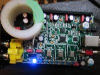
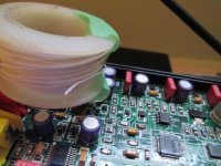
Leaf Audio XMOS 384k 32bit DAC: PCM5102, TDA1308, PE-65x12
I got one of these beasties:
XMOS PCM5102 32Bit 384K Finished DAC Board W/ Headphone AMP
(They've got lots of pics of the board and close-ups of the xmos, dac, oscillators, spdif output, headphone amp)
XMOS USB 2.0 with PCM5102 DAC, TDA1308 headphone amp and PE-65x12 pulse trans for spdif out.
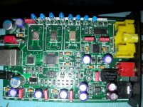
Hmmm, OSCONs, 3 oscillators, switch for USB or ext power and tight layout ... sounds good too!
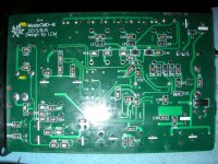
Back of the board:
The PCM5102 spec is too big so here's the url:
http://www.ti.com/lit/ds/slas764b/slas764b.pdf
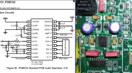
and here's how the DAC was implemented:
Headphone amp spec:
View attachment TDA1308.pdf
Spdif trans spec:
View attachment PE-65x12 pulse trans.pdf
So what do you think? Parts? Layout?
Any easy upgrades I can do?
Thanks and cheers,
Jeff
I got one of these beasties:
XMOS PCM5102 32Bit 384K Finished DAC Board W/ Headphone AMP
(They've got lots of pics of the board and close-ups of the xmos, dac, oscillators, spdif output, headphone amp)
XMOS USB 2.0 with PCM5102 DAC, TDA1308 headphone amp and PE-65x12 pulse trans for spdif out.

Hmmm, OSCONs, 3 oscillators, switch for USB or ext power and tight layout ... sounds good too!
Back of the board:

The PCM5102 spec is too big so here's the url:
http://www.ti.com/lit/ds/slas764b/slas764b.pdf
and here's how the DAC was implemented:

Headphone amp spec:
View attachment TDA1308.pdf
Spdif trans spec:
View attachment PE-65x12 pulse trans.pdf
So what do you think? Parts? Layout?
Any easy upgrades I can do?
Thanks and cheers,
Jeff
The grounding point of the output filter caps is going to be critical to the sound, but I can't see them. Are they on the reverse side?
If they're C59 and C60 then its looking like they're using a local earth which will be dirty by virtue of CM noise currents in the connecting cables..... First issues to clean up are grounding of the two digital inputs, next is power supply decoupling.
If they're C59 and C60 then its looking like they're using a local earth which will be dirty by virtue of CM noise currents in the connecting cables..... First issues to clean up are grounding of the two digital inputs, next is power supply decoupling.
Last edited:
The grounding point of the output filter caps is going to be critical to the sound, but I can't see them. Are they on the reverse side?
If they're C59 and C60 then its looking like they're using a local earth which will be dirty by virtue of CM noise currents in the connecting cables..... First issues to clean up are grounding of the two digital inputs, next is power supply decoupling.
since it seems to be a 4 layer design it could be difficult to change that much...
Gr GJ
Works wonderfully, fed it 44, 96, 192k ... nice!
Ummm ... where can I get some 384k 32bit?
To get higher sample rates you can use the ASIO driver in foobar.
The grounding point of the output filter caps is going to be critical to the sound, but I can't see them. Are they on the reverse side?
If they're C59 and C60 then its looking like they're using a local earth which will be dirty by virtue of CM noise currents in the connecting cables..... First issues to clean up are grounding of the two digital inputs, next is power supply decoupling.
Hey 'Braxi, finally got back to this:
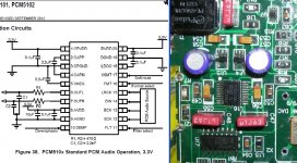
Yep, it's R7 and R21 and C59 and C60:
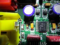
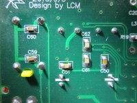
(PCM is under C61 and C62)
Could I put C59 and C60 on top of R7 and R21 and then run a wire back to pin9 of the PCM5102 (AGND)?
If my solder-fu isn't good enough for the SM PCM pins, what the next best, easy place?
Cheers,
Jeff
Last edited:
Too impatient and slightly soused to wait for sage advice ... 
Trying to figure out where pin 9 AGND goes ...
Buzzed out to the "bottom" of C62 ...
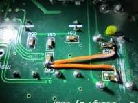
removed the caps ... then realized how small they are and ... put them back! probably burned em
cut the traces to the RCAs
straps back to the ?AGND? ( "bottom" of C62)
hack n slash!
Trying to figure out where pin 9 AGND goes ...
Buzzed out to the "bottom" of C62 ...

removed the caps ... then realized how small they are and ... put them back!
cut the traces to the RCAs
straps back to the ?AGND? ( "bottom" of C62)
hack n slash!
Last edited:
Seems to be plug-and-play on Win XP.
Identifies it as:
XMOS Audio 2.0 Output
in Windows volume
and Foobar output.
Works wonderfully, fed it 44, 96, 192k ... nice!
Ummm ... where can I get some 384k 32bit?
If you look at the version of XMOS driver from this unit, it maybe obsolete, it ranges from V1.61 to V2.19. This driver is not the same as that provided by XMOS's driver site. I think your driver is similar to that used by Weilliang XMOS.
I tried both Weilliang driver on my Chinese XMOS, USB to SPDIF adapter it seems to work, V2.19 sounds better than V.161. I can heard the difference.
Pffft! that official plenum grade Cat5! (T approve mid 90's teflon coated Cat5)
I loved that stuff too, in the mid-90s
Thin wire is fine for handling pretty much any frequency relevant to audio. Otherwise audio signal transformers and mH-range inductors would never work. The problems with very thin wire (<0.1mm diameter) seem to me to be with the insulation, not the wire itself. But you'll not encounter those problems in this application. What's the insulation on your magnet wire?
I loved that stuff too, in the mid-90sUsed it for running signal and power to active speakers. But I don't use it for cutting and strapping SMT PCBs - too much stress induced on the SMT parts.
Thin wire is fine for handling pretty much any frequency relevant to audio. Otherwise audio signal transformers and mH-range inductors would never work. The problems with very thin wire (<0.1mm diameter) seem to me to be with the insulation, not the wire itself. But you'll not encounter those problems in this application. What's the insulation on your magnet wire?
I'm concerned about the ability of awe 36 magnet wire handling MHz filtering, ...
?!?
- Status
- This old topic is closed. If you want to reopen this topic, contact a moderator using the "Report Post" button.
- Home
- Source & Line
- Digital Source
- Leaf Audio XMOS 384k 32bit DAC: PCM5102, TDA1308, PE-65x12
