I'm looking for some help with my CDP-101. Also, this is my first post! (woo).
I've picked up a very unwell CDP-101 on that auction site everyone loves. It's got a bunch of problems but I seem to be getting there slowly..
So far I've repaired the PSU (bad cap, corroded solder joint) using bridge wire and a couple of parts.
There's 2 other issues I have with the player..
1) the CD spindle doesn't spin.. This is my main issue
2) the eject drawer has a cracked gear.. I guess the previous owner wanted their CD back.
So, here's what I've tried so far on the spindle motor board and what happens when I insert a disc.
When I power up, the player comes on as what seems normal, I press the CD eject button, the tray comes out (assisted by me) with the disc clamp gearbox functioning correctly. I place a CD in and press the close button, again the cogless motor spins and I assist the drawer shut. The clamp then comes down, the laser gets a positive read of the CD in place and attempts to spin up the motor. This to me indicates at least the laser diode, focus driver and a few other parts are working. Also, I have wound the laser sled back and found that it seems to move ok indicating that the problem part there seems to work also.
So, on to the motor. I've taken the disc motor assembly out and metered all of the solder points and have found them to be fine. The passives on the board seem to be ok too. The power into the board (+ / - 10 and + / - 5) seem to be fine too although a little high due to the non regulated psu.
However, that's where I've hit the wall and could do with a bit more help. Would it be worth following the service manual's calibration steps? With the motor out and a bit of propping up of a CD I seem to have a movement attempt on the motor but nothing with any power when the laser recognises the CD. Or is it likely I have a dead transistor or chip somewhere?
My copy of the service manual's a bit vague on the cd motor board. I assume it was a part where the whole unit would be swapped if it was broken.
My next step is to grab my oscilloscope and take a look at that side of things followed by possibly doing the calibration in the service manual but I thought I'd get a post on here going so I have some help along route.
Any help would be massively appreciated!
Its a long while since I worked on one of these. When you say it attempts to spin the disc motor does it seem to spin at approx the correct speed ? If so then the next step really has to be a scope and look at the RF signal in particular the amplitude of the off disc signal. It could still be a problem with the pickup at this stage. The other big big issue with the CDP101 was failure of the STK6922 ??? (from memory) power opamp chips that drive the focus and tracking coils. Worth checking the output of those DC wise. If there is significant DC then the coils in the pickup could well be frazzled.
It seems like the motor is trying to spin but doesn't revolve at all. Also with a bit of encouragement it doesn't seem to get going. I've pulled it apart and oiled the bearings etc but no luck. I don't think it's an issue with the laser, the focus seems very strong and it definitely does recognise a disc is there as without the CD and my finger in place it doesn't attempt to start the motor but with a CD sat there it tries to spin up.
I'm thinking its probably a stepper control chip of some sort but wouldn't know which chip it is as it's not in the service manual I have.
Any further ideas?
Thanks for your help!
I'm thinking its probably a stepper control chip of some sort but wouldn't know which chip it is as it's not in the service manual I have.
Any further ideas?
Thanks for your help!
Ok heres what I've picked up:
-10 is showing -7.3V under load, +10 is showing 11.5v, gnd at 0, -12 is showing -11.9, +12 is showing 11.7 and BSL is showing 10.3V.
Any ideas? It seems like my -7.3 might not be happy. Is it worth looking at that rail on the PSU? Maybe a bad cap somewhere? Any ideas which would probably save a bit of time. I have an ESR meter so might look down that route.
")
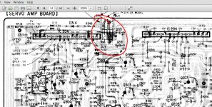
If you trace the -10 volt rail down it come to a fusible resistor R391. Is the -10 voltage OK and constant on the other side of that resistor ?
Is the disc motor PCB getting hot ?
Is either of the two STK6922 chips getting hot. Seem to remember these were mounted on the edge of the top ? PCB
Is the disc motor PCB getting hot ?
Is either of the two STK6922 chips getting hot. Seem to remember these were mounted on the edge of the top ? PCB
That doesn't sound good tbh.
Yes, you have to just check that the -10 volt rail isn't just half wave cycles due to a duff cap (scope will tell you that in seconds). The -10 rail is "rough" rail to power the current hungry motors/coils etc. Even at -7 it should spin like crazy with such a high control voltage.
Evidence so far is pointing to the motor.
You can look at the motor in isolation. If it has its supplies (and they are not critical at all) and the speed control pin goes high then the motor should take off.
Confirm the -10 rail is reasonably clean first but other issues would surely show if it were not.
If the motor proves faulty then it still might be fixable to component level.
Confirm the -10 rail is reasonably clean first but other issues would surely show if it were not.
If the motor proves faulty then it still might be fixable to component level.
Just having a good look for it.. Is it on the top of bottom Pcb or the psu?
I thought they were on the top at the back edge (been 20+ years since I've worked on one) but from your measurements so far (assuming the -10 is clean-ish) then I'd be looking at the motor
I can't seem to find that resistor. The top PCB seems to have numbers in the 300 range R315 seems to be a bit corroded by the adhesive so that'll need replaced. Not sure it's related though. The motor components don't seem to be getting hot.. slightly warm but not hot. I'll keep looking for that resistor.
Don't worry about the voltage readings appearing different. That's not uncommon when chasing faults.
If you are happy that all the voltages are present on the motor (the four supplies) and that the control voltage is present then the motor appears to be faulty.
What I would do next is disconnect the control pin and feed it either via the wiper of a pot across the positive supply (to give a variable control voltage) or just connect it via a resistor to the +10 volt rail. Perhaps somewhere around 47k to begin with. I'm just wondering when the control voltage comes up to 10 volts or so, well, could that be too high ? and the motor locks out.
- Status
- This old topic is closed. If you want to reopen this topic, contact a moderator using the "Report Post" button.
- Home
- Source & Line
- Digital Source
- CDP-101 Repair