
tbla said:
....me too...
I see no problem.
Imagine you shake an apple tree.
The apples that fall down you sort into three categories.
The ones with little animals inside
 you stamp R1.
The ones which look acceptable
 you do not stamp at all.
The ones which look very nice
you stamp S1.Did you really think you get something much different when you pay a few bucks more for S1 ?
This ugly millipede in it's el cheapo plastic body...

They should have made a beautyful ceramic with gold plated leads and stamped it S3

Bernhard said:7 transformers is for one channel...
But I could get them eventually.
The caps, do they decouple a digital or analog voltage ?
So are audiophile or "digital" caps needed ?
Hi Bernard,
I have done a fair bit of development on transformer
I-V in DACs and transformers in general. So I will give
some experiences and hopefully you will not waste
any money
As stated elsewhere here, the higher the ratio the worse
the performance, however this also depends on the tranny
impedance and source impedance. If these are low a high(ish)
ratio tranny can perform well. I have used a Lundahl high
quality 1:5 mic IP transformer for I-V and it was way too
coloured. Nice and warm though, ultimately not satisfying,
a bandaid for poor dac designs.
There is too much information to try and squeez into 1 post,
so your best plan of attack is to go to Jensen transformers
website and download all their mic IP and MC IP tranny
data sheets. Compare the ratios against LF distortion when
working from a specified sorce Z. All jensen trannies are
designed to work from a specified source Z and into a specified
load with a specified snubber. They are also the lowest measuring
distortion trannies currently available.
Since they give full FR and THD data for all transformers
you can comparatively see which designs will be best
suited for your dac.
Work out how many dacs you need to parrallel into what load
to give a certain voltage swing. This load will be the source
Z driving tranny. Also remeber that for TDA1541, it is designed
to work into 0 ohm load, so the more voltage swing the more
the dac will produce additional distortion. It's a balancing act.
I have done all this many times and have basically come to
the conclusion that it is very difficult to design an optimum
transformer I-V that REALLY works well, however it can be done.
Do the research, get aquainted with the parameters and
devices and then get back to us. Right now you are making
guesses at best and will not get the best result.
As an end note, if you want super transparency, the only
transformer I would think of using is a Jensen or possibly a
Stevens and Billington. I haven't had any experience with S & B,
however I know Thorsten has used them so maybe speak to him
which one is their best and whether it is suited to your
application. If you look at the price of Jensens best transformers
you will get a shock, but this is not the place to be penny
pinching.
Good luck,
Terry
TDA 1541
Is it possible to implement a digitalfilter / oversampling ?
Any schematic around ?
I read that the non-os versions of TDA1541 could make problems with solid state amps and it is recommended to use them only with tube amps, because RF...
Also sine waves look like staircase...
Bernhard
Is it possible to implement a digitalfilter / oversampling ?
Any schematic around ?
I read that the non-os versions of TDA1541 could make problems with solid state amps and it is recommended to use them only with tube amps, because RF...
Also sine waves look like staircase...
Bernhard
I read that the non-os versions of TDA1541 could make problems with solid state amps and it is recommended to use them only with tube amps, because RF...
Just try non os and you'll discover that it isn't that bad although when you measure the DAC you'll fall of your chair.
I was worried about that too but never experienced desastrous effects.
BTW R1 means R(elaxed ) specs IIRC. That's the common explanation anyhow. Rejected parts wouldn't have made it onto the market. Not with Philips in that time. Rejected parts are usually thrown away.
Re: TDA 1541
If you are using transformer I-V that will be sufficient
LPF. Even into SS amps.
Cheers,
Terry
Bernhard said:Is it possible to implement a digitalfilter / oversampling ?
Any schematic around ?
I read that the non-os versions of TDA1541 could make problems with solid state amps and it is recommended to use them only with tube amps, because RF...
Also sine waves look like staircase...
Bernhard
If you are using transformer I-V that will be sufficient
LPF. Even into SS amps.
Cheers,
Terry
Actually one item of the specs is better for R1. Forgot which one.
Sure there are, they were used with SAA7220P/B ( 4 x fs ) digital filter as a standard in millions of cdplayers of all kinds and brands.
Just find a SAA7220P/B ( Google for the datasheet ), check a schematic of any cdplayer with TDA1541 and the SAA and connect the CS8412 to 3 right pins of the SAA7220P/B...Just like you do it now to the TDA. Feed the SAA with a sturdy supply as it throws out garbage on the supply lines. Do a Search for that here for more info.
I don't know if a SAA7220P/B can drive 4 TDA's. Silly plan IMO, why would you use 4 or more of these excellent chips *and* use oversampling to degrade the results !?!?!
There are not much alternatives for SAA7220P/B unfortunately. I quit searching for one.
Ok, thanks, still if there is a known schematic for TDA oversampling...
Sure there are, they were used with SAA7220P/B ( 4 x fs ) digital filter as a standard in millions of cdplayers of all kinds and brands.
Just find a SAA7220P/B ( Google for the datasheet ), check a schematic of any cdplayer with TDA1541 and the SAA and connect the CS8412 to 3 right pins of the SAA7220P/B...Just like you do it now to the TDA. Feed the SAA with a sturdy supply as it throws out garbage on the supply lines. Do a Search for that here for more info.
I don't know if a SAA7220P/B can drive 4 TDA's. Silly plan IMO, why would you use 4 or more of these excellent chips *and* use oversampling to degrade the results !?!?!
There are not much alternatives for SAA7220P/B unfortunately. I quit searching for one.
jean-paul said:
There are not much alternatives for SAA7220P/B unfortunately. I quit searching for one.
Various NPC SM584x
TI DF1704/6
jean-paul said:I should have specified I2S in, I2S out types.
A little logic and you are in business.

Could look like this
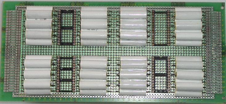
Seems that I will not use 7 but only 4 chips, so I have still the option to go balanced.
Maybe upgrade to 8 later.
This is my first try to get a DAC board layout, there is a ground plane on the upper side.
Just no space left for the TL431s, is it ok to put them on another board ?
PSU decoupling caps will still be on the DAC boad.
Or I put the TL431s on the backside.
The white caps are stacked 3 on 4, MKP 1839 1µF 1%, .
Can I use 1µF
mr. walt jung ended up with 1uF - as best compromise.......
tbla said:
mr. walt jung ended up with 1uF - as best compromise.......
Did he also test different cap types? And what was the result?
- Status
- This old topic is closed. If you want to reopen this topic, contact a moderator using the "Report Post" button.
- Home
- Source & Line
- Digital Line Level
- schematic with 4 or more TDA1541 parallel