All parallel TDA1543 solutions have a shared Vref and a shared Analogue Out I/V resistor.
However, the TDA1543 also can work with a current source to achieve the same Vref as using a resistor to get the Vref.
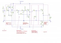
So I have come up with a scalable solution for paralleling TDA1543's. In fact, it will be possible to insert one to many of these chips without changing any components
My trick to obtain this independence is by using a current mirror for the Iref pins of each chip; this current source (or dump as some might say) is running independent for each chip.
Likewise, on the output I do not sum the bias - I maintain separate I/V resistors, just to sum only the AC part with an array of coupling capacitors.
Each chip is now electrically isolated from each other (not the Vdd of course).
Questions I have:
What improvements do you suggest?
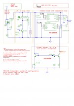
albert
However, the TDA1543 also can work with a current source to achieve the same Vref as using a resistor to get the Vref.
So I have come up with a scalable solution for paralleling TDA1543's. In fact, it will be possible to insert one to many of these chips without changing any components
My trick to obtain this independence is by using a current mirror for the Iref pins of each chip; this current source (or dump as some might say) is running independent for each chip.
Likewise, on the output I do not sum the bias - I maintain separate I/V resistors, just to sum only the AC part with an array of coupling capacitors.
Each chip is now electrically isolated from each other (not the Vdd of course).
Questions I have:
- what is the fan-out of an XMOS I2S reciever? How many chips can be added without seriously deteriorating the output rise time? The TDA1543 is rather tolerant some say.
- Should there be a damping resistor like 5-10 ohms in the receving bus for each chip for CLK, WS, DATA? Some schema's use such.
- Or should I go for a buffer stage on the input bus (hope not).
- I now have two variables: Vdd and Iref. Or should I maintain variable I/V? Hope not, no place for trimmers
- I do have a distortion meter so I can see how to set the values and what effect they have on the distortion.
- I plan to go with mild oversampling in the computer to say 88.2 KHz and add a mild lowpass at 40-50 KHz of 6dB
What improvements do you suggest?

albert
hi, thank you for your wonderful idea.
is l-out suppose to be tied to vref? and what benefit do you suppose there will be compared to ecdesign's solution of biasing rload resistors leaving vref floating?
Iout is independent of Vref because I still have a discrete I/V resistor, but several in parallel.
- What is ECDesign's solution. Can you link to it?
So only with a current source this solution of an active follower with an opamp would work.
However with a FET follower (output connected to source) there would not be a problem with distortion because of a supplementary current. There would be a need for a separate bias for the fet.
Thinking about it, not a bad idea maybe, but I'd like to understand ecdesign's direction 
In what way does using a current source per chip instead of a Vref resistor per chip improve things? Doesn't it just add a little noise and complication?
I'm not sure if the noise of a CS like this (e.g.. 2SC1815, 2SC2240) would make it worse in the internal CCS banks than a resistor with it's temperature noise.
You could still AC couple the outputs in parallel.
The one advantage I look for is that I now can at my own choice add a chip or not without having to rebalance the whole thing.
Your CCS has resistors, typically of lower value than the Vref resistor would be. That means more thermal current noise. Plus transistor noise.
With a separate Vref resistor per chip, separate output resistor per chip and AC coupling, you can parallel as many chips as you wish.
It is not the CCS which allows you to parallel, but simply the fact that both Vref and output ports have 'per chip' arrangements and AC coupling.
With a separate Vref resistor per chip, separate output resistor per chip and AC coupling, you can parallel as many chips as you wish.
It is not the CCS which allows you to parallel, but simply the fact that both Vref and output ports have 'per chip' arrangements and AC coupling.
A 390 has less voltage noise than 2k2 but more current noise. Alternatively, in your circuit the voltage noise is amplified. Two different ways of looking at the same thing. You said you didn't want to use a resistor because of noise. I am just reminding you that your preferred solution has more noise. Probably still low enough, but I would not use a complicated circuit which has worse performance than a simple one - especially if the worse performance was in the very parameter I was worried about.
OK, I agree on issues of complexity, and I tested yesterday with a resistor.
Aimed at 1,75 mA and with a certain Rout (variable, best 2k13) I got a nice 2nd harmonics, which is in phase. Too little: Iref bumps through the bottom (sags) and too high distorts at the other end. There is quite some latitude.
DCpoint of A out: 3,7-3,9 volt; at 3,5V it is least.
Vb=6,95 V
What I want to see next is if various chips have the same Iref/Rref combination. If so, I'll gladly keep it simple.
I will have to apply a 44 kHz filter though to get rid of the quantization steps that spoil the result of measuring.
Alternatively I need a 100 Hz 0 dB sine in large quantities (minutes on end) because my distortion meter has a steep 250 Herz filter.
First the central position,
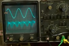
next the extreme of low with sagging,
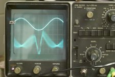
then the final choice with 2k13 and a higher 2nd.
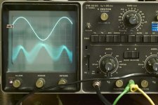
I have used the scope triggering; should use external triggering - that gives a better picture of the 'noise', now there is spurious flanks because of the steps.
Don't be baothered with the noise. It will disappear gradually. I promise!
albert
Aimed at 1,75 mA and with a certain Rout (variable, best 2k13) I got a nice 2nd harmonics, which is in phase. Too little: Iref bumps through the bottom (sags) and too high distorts at the other end. There is quite some latitude.
DCpoint of A out: 3,7-3,9 volt; at 3,5V it is least.
Vb=6,95 V
What I want to see next is if various chips have the same Iref/Rref combination. If so, I'll gladly keep it simple.
I will have to apply a 44 kHz filter though to get rid of the quantization steps that spoil the result of measuring.
Alternatively I need a 100 Hz 0 dB sine in large quantities (minutes on end) because my distortion meter has a steep 250 Herz filter.
First the central position,

next the extreme of low with sagging,

then the final choice with 2k13 and a higher 2nd.

I have used the scope triggering; should use external triggering - that gives a better picture of the 'noise', now there is spurious flanks because of the steps.
Don't be baothered with the noise. It will disappear gradually. I promise!
albert
There is bound to be a bit of variation. With a supply voltage at the upper end of the valid range you should have enough leeway to use a fixed resistor. At lower supply voltages it might need adjustment for each chip.triode_al said:What I want to see next is if various chips have the same Iref/Rref combination. If so, I'll gladly keep it simple.
Have you seen my web page on passive I/V for the TDA1543?
Last edited:
There is bound to be a bit of variation. With a supply voltage at the upper end of the valid range you should have enough leeway to use a fixed resistor. At lower supply voltages it might need adjustment for each chip.
Have you seen my web page on passive I/V for the TDA1543?
Yes, and it was a great inspiration.

The diagrams are clear. And where you enter the area to the right of the crosspoint at a specific voltage, then there is indeed some 'leeway', or latitude, for the component values. This allows the selection of a point with a nice amount of 2nd harmonic, such as 0,5%.
Too little is a bit bland.
Just a build on your page, - You might also mention that the voltage on the "Vref pin" is about 2,15 Volt independent of the Iref. [i.e. 2,15 V at 7 Volt; haven't measured now at other Vdd's]. A diagram would taker away the myth of a voltage sensing pin immediately! In the Philips implementations the Vref is the reference for the to the output follower, the I/V converter. This is the base voltage to force the AOL, AOR to with the opamp, if I say it correct.
In the past I monitored the voltage on the Vref pin and indeed couln't get a clue what I was doing  but still at the end after a lot of experiments it sounded good. Sometimes the latitude was so small that it could just runaway and the DAC would stop working

I had the advantage of having some Philips CDP's with the TDA1543. It was great to see the improvement when adding a super low jitter Tent-clock. The effect was here more pronounced than in other players.
The TDA1543 is great, but a bit wild at times. I remember a tweaked machine where we just came from a concert, bought the CD and could recreate the whole live stage and dynamics at fortissimo with this chip. Other chips in comparison are much more subdued...
I prefer bland. Note that you need to be careful that your 0.5% 2nd does not come mainly from asymmetric clipping as this will give you lots of higher order distortion too - not nice!This allows the selection of a point with a nice amount of 2nd harmonic, such as 0,5%.
Too little is a bit bland.
It never occured to me that people might think otherwise. The data sheet makes it clear that this is a voltage output from the chip.You might also mention that the voltage on the "Vref pin" is about 2,15 Volt independent of the Iref.
ECDesigns bias tweak can be found here.
http://www.diyaudio.com/forums/digi...-tda1541a-286.html?postid=1813308#post1813308
Pin 7 is left floating and +3v from a couple of 1.5v batteries is fed to the other two resistors (Pins 6 & 8).
Best 50p I ever spent!
http://www.diyaudio.com/forums/digi...-tda1541a-286.html?postid=1813308#post1813308
Pin 7 is left floating and +3v from a couple of 1.5v batteries is fed to the other two resistors (Pins 6 & 8).
Best 50p I ever spent!
As the chip is designed to have a current drawn from Vref I can't see what problem there is in actually doing this. If a resistor to ground will inject too much noise, as alleged, then ground is too noisy anyway so we are stuffed. Sending the output to an elevated supply rather than ground is a good idea, and brings even passive I/V a little closer to the datasheet circuit.
ECDesigns bias tweak can be found here.
http://www.diyaudio.com/forums/digi...-tda1541a-286.html?postid=1813308#post1813308
Pin 7 is left floating and +3v from a couple of 1.5v batteries is fed to the other two resistors (Pins 6 & 8).
Best 50p I ever spent!
It of course highly surprises me that the pin could be left floating at all and the bias is still correct.ECdesigns: Same applies for Vref (pin7) if this pin is connected to anything, sound quality degrades dramatically. This is caused by ground or power supply noise polluting both bias current source and DAC output current, then it's over. So never ever connect this pin!
Then by inference the Vb must be 5 volts I guess. Only variable is then Rout; and reducing the voltage to out with a 2,9-3,1 volt bias is interesting too. ECdesigns uses a rather low 680 ohms (low for one chip); the current though is not too high because of the bias of 3V.
I had been thinking myself that the output - that tries to dump a certain current (specs: -0,6 - +5 mA) could also be connected to a current source, the rest then being high impedance for the AC current; and the Aout resistor then being adjustable for level + distortion.
I'm still thinking about that. Some form of diplexer, perhaps?
For high-rate streams the filter can be quite simple.
I like the filter that Philips implemented in all their players.
The stock implementation is bad bad
But I have used the following filter electronics in my TDA1541 setting:
here is the basis of my filter, it is 40 kHz LP; at 20 kHz it is less than 0,2 dB down from flat:
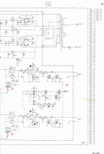
It is like the filter in the later CD950 - note slightly other values:
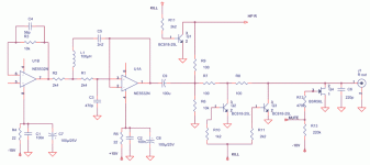
The buffers are based on the article by Jean Hiraga on the Kaneda electronic 3-way filter, as published in L'Audiophile (version 1985). All passive.
The result is a very flat response and while I can't measure the phase, it is claimed to have nice characteristic.
The filter does not have a NOS shelving, because the SAA7220 seems to have (is said to have) the shelving built into its digital filter.
Anyway the combo is rather natural and though not in far like my vinyl in depth it is quite good (not being sarcastic). I refurbished the components from a CD160; the unit I found on the flea market had a TDA1541 S1
Yes, a higher LP point could be used. Though Philips says one goal is to get rid of the 44.1 residues that would still appear with oversampling and a gentle slope - even though Accuphase seems to have made quite a nice sounding implementation of a 88KHz 6 dB LP filter.
Its interesting to read here that ecdesigns has found the same as I have - that TDA1543s sound best with nothing connected to pin7. I have just posted on my blog a mod to a cheap 1543 SDcard player where I created a 3.75V reference from a TL431, filtered it passively and then used this quiet voltage source as the AC ground for the I/V resistors. It obviates the need for the internal bias current sources. The soundstage improves quite a bit for such a cheap and simple mod.
I also have some passive filters on the blog - I started out with elliptical designs but now reckon the easiest kind to build is a high-order chebyshev. Thanks to ecdesigns pointing out a very handy passive filter design widget online
I also have some passive filters on the blog - I started out with elliptical designs but now reckon the easiest kind to build is a high-order chebyshev. Thanks to ecdesigns pointing out a very handy passive filter design widget online
Last edited:
abraxalito, what about when using active i/v such as ad844? can the pin referenced to anything besides the i/v resistor?
i've also found the chip to sound much better with pin 7 floating. it's even possible to connect vref to the center tap of the line transformer if you're using 1:1:1:1 or such. i still haven't been successful running two 1543 in such manner with differential output, however...
i've also found the chip to sound much better with pin 7 floating. it's even possible to connect vref to the center tap of the line transformer if you're using 1:1:1:1 or such. i still haven't been successful running two 1543 in such manner with differential output, however...
- Status
- This old topic is closed. If you want to reopen this topic, contact a moderator using the "Report Post" button.
- Home
- Source & Line
- Digital Source
- TDA1543 semi-parallel solution