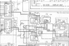
Hello. Trying to attach schematics of the DAC/ IV-stage of my Denon DCD-2560. (hope it works...)
What I really could need some help with is:
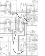
If You look at the left channel, there are two AD1862 DAC's, each one is feed into its own corresponding OP-amp (IC315/IC317) (buffer?), and further into one OP-amp named IC311. (the right channel is like)
Is it possible to take the signals from the AD1862's, and feed it directly into the I/V converter from the D1. (Schematics at www.passlabs.com ), and get a balanced output.
I am aware some of you don't like CAP's in the signal path, but if htis could work, I am pretty sure it would SOUND pretty amazing compared to the original Denon I/V !!!?
My problem is that i am not sure if the DAC's is originally balanced, or just some strange (?) form of OS....
All the best....and please...HELP")
What I really could need some help with is:
If You look at the left channel, there are two AD1862 DAC's, each one is feed into its own corresponding OP-amp (IC315/IC317) (buffer?), and further into one OP-amp named IC311. (the right channel is like)
Is it possible to take the signals from the AD1862's, and feed it directly into the I/V converter from the D1. (Schematics at www.passlabs.com ), and get a balanced output.
I am aware some of you don't like CAP's in the signal path, but if htis could work, I am pretty sure it would SOUND pretty amazing compared to the original Denon I/V !!!?
My problem is that i am not sure if the DAC's is originally balanced, or just some strange (?) form of OS....
All the best....and please...HELP
Attachments
Hi Lyra,
The IC315/IC317 are I/V converters (it is strange the dual opamps are put inside but both have one half left unused; these converters also have strangely high value I/V resistors and then the signal is attenuated). The IC311 converts the signals to SE.
I am not very familiar with AD1862 (nor with PCM63 nor D1) but looking briefly I’d say it shouldn’t be a problem to replace this I/V with that from D1. For the AD1862 you’ll need a higher value I/V resistors than those used in D1.
Pedja
Be very careful when working with the '1862s. They are very static sensitive, and if you operate them without a load, they will fry.
If the MSB trim is properly set, it will be good for he life of the part.
They are not cheap, so don't ruin them!
(I like them.....in some ways easier to work with than B-Bs.)
Jocko
If the MSB trim is properly set, it will be good for he life of the part.
They are not cheap, so don't ruin them!
(I like them.....in some ways easier to work with than B-Bs.)
Jocko
Pedja said:Hi Lyra,
I am not very familiar with AD1862 (nor with PCM63 nor D1) but looking briefly I’d say it shouldn’t be a problem to replace this I/V with that from D1. For the AD1862 you’ll need a higher value I/V resistors than those used in D1.
Pedja
Which resistors are you referring to ? (R26 and R33??), and what should the value be ??
All the best!
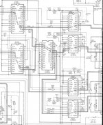
Attachments
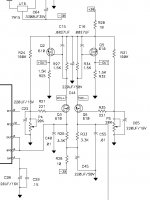
I/V resistors are R27 and R34. However, raising their values the operating points will be changed. It will take some time to find the best new operating point. Using the circuit as it is with AD1862 you’ll have about 1V RMS out per phase. You did not tell what you’ll do further with this balanced signal, but it might be enough as well.
Pedja
Pedja
And....
-when making a new powersupply to this I/V-stage....a 15-20VA toroid transformer would be enough, wouldn't it?.
How much current do i have to expect/ calculate for with the use of two of theese cirquit's?
-As for the I/V resistors in the original Denon drawing, is this R811, and R813 (9k1) ?
-What kind/size of resistors would you recommend for the D1, and what kind of results will this accomodate ?
-The JFET's in the D1-stage have to bee matched, but if i buy matched JFET's (e.g. 2sk389 dual Jfet's), and use this ones so that Q2, and Q5 are matched, and also Q3, and Q6 are matched, this would be good enough or ??
PS: I don't feel to confident that i have figured it all out (or even enough.. ..) yet, regarding theese kind of cirquets. I don't have an intension of reinventing the wheel, just to get the maximum out of my sound-system.
All the best
-when making a new powersupply to this I/V-stage....a 15-20VA toroid transformer would be enough, wouldn't it?.
How much current do i have to expect/ calculate for with the use of two of theese cirquit's?
-As for the I/V resistors in the original Denon drawing, is this R811, and R813 (9k1) ?
-What kind/size of resistors would you recommend for the D1, and what kind of results will this accomodate ?
-The JFET's in the D1-stage have to bee matched, but if i buy matched JFET's (e.g. 2sk389 dual Jfet's), and use this ones so that Q2, and Q5 are matched, and also Q3, and Q6 are matched, this would be good enough or ??
PS: I don't feel to confident that i have figured it all out (or even enough..
..) yet, regarding theese kind of cirquets. I don't have an intension of reinventing the wheel, just to get the maximum out of my sound-system.All the best
Expect about 15mA per phase i.e. 30mA per channel.
Yes, 9.1k are I/V resistors and these give quite high output voltages that are attenuated with 4.3k/2.2k dividers and then with 6.8k/3.3k divider and... (signal goes out of the sch).
610 are IRF610 MOS-, not J-FETs.
No idea about Electrocompaniet. But if you are not sure what to change and how, it would be best to make the circuit as it is, I guess it is well tuned to its sweet spot. It is not a problem to make the circuit working with higher value I/V resistors (generally you should alter R26/R33 to ensure proper biasing and scale C15/C16 to match the new I/V resistors) but you’ll have more to do to make it give its best.
Pedja
Thanks Pedja!
I think this will help me a lot.....i think i build the D1 as is, and try it. Then if the signal is too low i try to modify it.
As for Jocko Homo: "If the MSB trim is properly set, it will be good for the life of the part" i'll try to find out about this, but i don't think i have the right tools needed for this adjustment, but then again i am not sure what tools needed. Maybe it's not all that much tho....
Thanks!
As for the powersupply for the D1.....
There have been a lot of discussion on this board related this subject, and what regulator is best suited for a specific circuit, LM1085 (?), 317, "not tree pin regulators", etc.
Anyone have a clue what regulator would be best suited for this I/V stage??
I was just thinking.....why don't build it "right" the first time...
All the best....
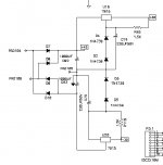
....and this is the original D1 +-30V-power (i think) 7815, and 7915!?, :
There have been a lot of discussion on this board related this subject, and what regulator is best suited for a specific circuit, LM1085 (?), 317, "not tree pin regulators", etc.
Anyone have a clue what regulator would be best suited for this I/V stage??
I was just thinking.....why don't build it "right" the first time...
All the best....
....and this is the original D1 +-30V-power (i think) 7815, and 7915!?, :
Attachments
Hallo Lyra,
I builded some time ago the I/V converter and used the mosfet followers to power it like you can see they in the Passdiy Bosoz preamp PS.
Just use a bigger gate resistor , 2.2k instead of 220 , it will take more margin from high freq oscillations and more clean supply.
At that time I used also CCS for R26 and R33.Yes , it is a best start to build the circuit as it is , but with patience some changes are possible . The current through each halve is 10mA.
MSB trim......
You will need a test CD with a test tone, about -60 dB, and a 'scope.
Adjust the MSB trim for the lowest distortion, which can be seen on a 'scope.
Do not do it with a 0 dB signal, as you will find in most service manuals. It will be wrong. Trust me on this one.
Jocko
You will need a test CD with a test tone, about -60 dB, and a 'scope.
Adjust the MSB trim for the lowest distortion, which can be seen on a 'scope.
Do not do it with a 0 dB signal, as you will find in most service manuals. It will be wrong. Trust me on this one.
Jocko
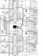
Lyra said:What if I do as i have tried to edit in the drawing below, would I get a balanced signal without oversampling ???
All the best !
BTW: I have searched Google for CF37606, BUT NO HITS...
No. You will get 8x oversampled data. You need to tap the data before the CF37606.
ray.
Re: MSB trim......
-Where do I get a CD with this testtone?
-Do I measure on the line-output ?
-Do I have to readjust this when the I/V-stage is changed/ replaced ?
-Should this -60 dB testtone be a single sinus (eventually preferred freq.),
white noise, or pink noise ?
(Below is from: http://www.diyaudio.com/forums/showthread.php?s=&threadid=17581&highlight= )
Does this mean that I should get a better sounding CDP if I do as edited in the schematic below ????
If I do that, could I run the unused outputs through the original I/V-stage, or could I mount them in some kind of parallell as seen with other DAC's.
Jocko Homo said:You will need a test CD with a test tone, about -60 dB, and a 'scope.
Adjust the MSB trim for the lowest distortion, which can be seen on a 'scope.
Do not do it with a 0 dB signal, as you will find in most service manuals. It will be wrong. Trust me on this one.
Jocko
-Where do I get a CD with this testtone?
-Do I measure on the line-output ?
-Do I have to readjust this when the I/V-stage is changed/ replaced ?
-Should this -60 dB testtone be a single sinus (eventually preferred freq.),
white noise, or pink noise ?
(Below is from: http://www.diyaudio.com/forums/showthread.php?s=&threadid=17581&highlight= )
Õàëÿâùèê said:Don`t use R-2R parallel or balanced. A single DAC per channel is perfect. Parrallel or balanced R-2R DAC will kill a sound. Better use trim circuit for tuning LSB.
Does this mean that I should get a better sounding CDP if I do as edited in the schematic below ????
If I do that, could I run the unused outputs through the original I/V-stage, or could I mount them in some kind of parallell as seen with other DAC's.
Attachments
BTW: I forgot to mention that I tried to mount the ZAPFilter in balanced mode, but I don't like the result.
The player played as before, kind of harsh and unmusical. The sss-sounds was NOT good...wery annoying actually!!!!!.
I am using the ZAPFilter in another player right now, and this is definitly not harsh. Actually smooth sounding....like the sound of this, but it was the Denon I was hoping to use...
Don't know if this harshness (?) come from not adjusted MSN on the DAC's, or the balanced configuration, or a combination.....or somethin else....
Would appreciate ideas !!!
All the best!
Lyra
rfbrw said:If you want to run the cd player in balanced mode, you will have to bypass the SM5828 shift-register. This shift register applies a delay of 24 bitclock cycles for two of the dacs in a manner similar to Wadia.
ray.
Not nesseserely....balanced. According to Õàëÿâùèê I should not use R-2R parallel or balanced. Parrallel or balanced R-2R DAC will kill a sound. Better use trim circuit for tuning LSB.
Don't know enough about this DAC to know if this is true.
If there are possability gaining better sound without balanced DAC's I go for that solution. The remaining DAC's could for instance:
1: be mounted in parallell (interesting thought...) ?
(TDA1543, TDA1541(?), and AD1955 are seen in parallel operation to obtain higher linearity !?)
or
2: drive the original I/V stage, and thereby the headphone jack... ?
Whatever I have to do to gain maximal sound quality.
What is the purpose with the SM5828 shift-register anyway ? What will happen with the sound if I bypass this ??
- Status
- This old topic is closed. If you want to reopen this topic, contact a moderator using the "Report Post" button.
- Home
- Source & Line
- Digital Source
- Need help with this I/V stage replace...