Well, not quite ATX as it doesn't fully conform to the standard but certainly does the job.
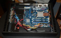
Some time ago i bought a Streacom fanless case and built a small headless music PC around an Intel DH77-EB board with i3 3220T low power processor. It was meant to replace and possibly improve upon a Dell i5 XPS laptop.
The PC is wired to a router and plays music files off the network through a USB port. The usb/dac side has galvanic isolation of the I2S signal and two levels of reclocking, so should be very immune to the source.
Built with a "nano" power supply, initial results were not encouraging. Despite being fanless and spinning-disk-less it sounded worse than the Dell laptop. The nano is similar to the better known pico - a tiny 80W switcher which takes 12v and produces the required ATX voltages and logic. The first step was to improve upon the 12v raw dc.
Replacing the raw dc with a linear PS regulated to 12.6v proved the most significant step towards better sound. Now the fanless box was indeed a better source than the Dell. It stayed like this for months and generally performed up to expectations.
Of course, got itchy fingers again, so the "nano" had to go. The motherboard i use may be much easier to power up than more sophisticated boards. It only requires backup power to be applied before any of the other voltages. So, +5v backup is delivered by a 7805 - shown on the circuit as an LT1117-5. All other regulators are off before the power button is pressed. Well, not quite off - down to 1.25v as it was much easier to control the regulators like that, but it doesn't seem to make any difference.
The right hand side sink of the case takes care of the processor cooling and barely gets warm. My regulator proto-board is mounted on the other sink and probably gets up to around 40C at 25C ambient.
Compared to the nano powered from a linear supply this is a bit better, mostly in low bass, ambience and soundstaging. It is certainly not a night and day difference. Would i build it again? Yes, in a flash 🙂
It may be interesting to increase the number of regulators, so, per example the SSD would get its own power. It may also be possible to circumvent some of the MB switchers, possibly apply 1.5v directly to the memory. Got too many other projects to pursue at present, but maybe one day...
Attachments
I'm really interested in this. I am using an ASRock Z87E-ITX board with an Intel Haswell 4570T processor. The board has an ATX power supply socket and at the moment I have a PicoPSU in it. We have the same case (which I really don't like the finish of but I'm using it for now).
I'm very much a novice when it comes to building electronics but I want to learn. At the moment I am doing the simplest of mods to send cleaner power to the SSD just by using a Velleman K1823 to take the 12V input down to 5V for the SSD.
My next step was to be similar to yours - using a brick to send, say, 15V instead of 12V and regulating this down to 12V (why did you use 12.6V?) for input to the PicoPSU.
Can I ask some basic questions?
Aren't the LM7805 and LT1117 very low current? How much current is being delivered to each of the voltages? I guess you don't need much for the standby but what about the +12V? How much current is input? (+17V)
Presumably your step 1 of delivering regulated 12V was a simply set up of +17V in, a capacitor, an LT7805 and another capacitor on output? What capacitors would be suitable for this?
(why did you use 12.6V?) for input to the PicoPSU.
This is the voltage i measured coming out of the brick and is also the highest that the nano will take. It was 6 months ago, but if i recall correctly i tried raising the output voltage as much as possible in order to minimise the power dissipation across the regulator and still leave a 3 volt drop.
As for your question about the power consumption -i don't have an exact answer and i have not measured the current draw on the different rails. And it will depend upon processor load and whether any devices are powered from the USB ports. And what MB devices are active...
So, based on my initial test - to build a linear PS for the nano using a single LT1085 regulator (3A) i concluded that a single regulator for each of the rails will be more than sufficient. As i use a single input voltage of around 16.5-17v, the worst power dissipation occurs at the 3.3v and 5v lines. But nothing particularly noticeable. Heatsink remains lukewarm. Splitting the input power between two transformers will further reduce the stress on the regulators and may, who knows, bring even some sonic benefits. In any case the raw dc is the weakest link at present - it uses a single 15mF smoothing cap and at the expected current draw of around 3A this obviously leaves a lot of ripple.
As for the finish of the Streacom case - it is beyond horrible, especially the top cover. Manufacturing niche products like this is probably a high profit margin business and the distribution channels of such goods are way more expensive than for normal PC cases. With hindsight i would rather have used a slim amplifier case.
Your circuit diagram has an LT1117 for the 12V. Is this just a typo and should be another 3A LT1085? (You mentioned the correction to the +5V standby but not this.)
Having done some reading on NPNs I think I understand how you delay the delivery of +12V/+5V/+3.3V. Do I have the following correct? You need voltage pressure on each of Q1, Q2 and Q3 for the circuits to be closed and +12V/+5V/+3.3V to be delivered. This comes when the mobo has been taken out of standby via the chassis front panel switch and voltage is applied via PowerOn (ATX pin 16). Presumably your +5V goes to the ATV +5V input pins (4, 6, 21-23) as well as Power Good (pin 8).
When you "replaced raw dc with a linear ps regulated to 12.6V" how many amps did your regulator handle? My PicoPSU brick is 12V, 12.5A.While I doubt I would draw anywhere near 12.5A I was thinking I would have to deliver more than 3A (to be safe). I would also have thought that 12.6V (measured) versus 12V is error on the part of the brick because I understand the PicoPSU merely passes the 12V untouched.
No diode ahead of the initial caps? (I thought this was advisable)
Sorry for the dumb questions!
Nothing dumb.
Indeed it is the LT1117 equivalent - a 317 that i used. Apparently the +12v supply is, in my case, very lightly loaded.
Your understanding of the circuit is correct. The "power good" signal is tied to the +5v rail. Such delay - the ramp of the regulator output, slightly delayed by the cap on the adjust pin - may not be sufficient for all boards, but it works perfectly with mine.
In fact the whole setup has been super stable for a few weeks now. Of course there can be no guarantee it will work on a different board, as the ATX 2.2 specs are clearly not met. Still, in the relative absence of published circuits of this type, it is probably a good starting point. One can readjust delays or up the current on the regs by just opting for a 1084.
Thanks a lot
Probably little demand for 12Vwithout any moving devices (fan, optical drive, spinning HD etc).
Is there a cost attached to moving to a 1083? I don't mean the unit cost of the regulator but rather from a design or ripple perspective.
PS: On enclosures, check out HD-Plex or even Modu.it (albeit the latter doesn't have built in heat sinking)
An elegant solution analog_sa. I have very similar system and am experimenting with individual PSUs switched with relays (using my original pico psu to supply the 5v standby and to trigger the relays). I have also split out the P4 connector to a separate 12v rail resulting in another step forward in SQ and I power the RAM separetely with a dedicated 1.5v feed...again a small but nice improvement. You're right it's not night and day when compared with replacing the original 12v brick but I agree that it's worth it. My rails are aiming to supply 2A continuous but 5A peaks. (I use JPLAY which ramps up the power requirements as it makes the CPU run full tilt when playing music).
I'll try to post some pics if anyone's interested but might have to wait for a bit.
Cheers,
Crom
PS Before someone asks, I have no double-blind test results or anything else that qualifies this above a waste of time but I trust my ears enough to know when I've gone wrong or am indeed wasting my time and it sounds pretty good to me ;-)
I'll try to post some pics if anyone's interested but might have to wait for a bit.
Yes, yes 🙂 Please.
Could you also provide details re the 1.5v injection? Any MB surgery?
Separating the 12v for the processor is easy and is something i will definitely test, thanks for the encouragement.
Not sure why i opened this here and not in "PC based" Maybe a moderator will be kind to move it.
What type of capacitor is suitable for this sort of project?
Not too sure, really. As there is bound to be plenty of decoupling capacitance and very likely switchers too on the MB, not sure it matters a whole lot. Now if motherboards came with a circuit... 🙂
An what about the noise generated inside the mother by the digital signals? Noise by the SMPS is ultra-audible, noise in the mother system may not. Also SMPS noise i relatively fixed in frequency, mother noises doesn't ‼
Ehm, what about? 🙂
One bit at a time. If we cannot design the MB, let's at least do what we can.
Crom's post indicates that he has removed one of the MB switchers. Whether it's possible to take them all out i have no idea, it probably is very MB specific.
Otoh, MBs are designed with care for PS and RFI emissions, are they not? Groundplanes, multilayers, software optimisation and simulation at RF. Maybe on-board generated interference is less harmful than quickly hacked together high power switchers like the nano or pico...
Not sure how true this is, but i distinctly remember a manufacturer of high end music servers touting custom designed, switcher-less MBs...
There are various guys on here that I've talked to (eg Mace...sorry, might be Marce) on here who are clearly v knowledgeable about smps and I am sure it's possible to build an excellent quality smps (it must be...the hypex amps sound great). I've done some research but I'm in the following rather than pioneering camp at the moment and until I have something I can follow and then experiment with I'm going to stick to linear.
I don't entirely agree with Osvaldo that the MB smps noise is audible but the sound I've got out of my motherboard has certainly improved when I've got rid of smps where possible.
analog_sa: I can't post pics but take a look in the computer audio section of audio asylum and I think i posted some direct links in the computer audio section of the jplay.eu site. There's plenty of reading to do in both of those. AA is especially DIY friendly and that's where I got the RAM tip from.
Basically, the idea is that you remove the coil that is part of the RAM SMPS (there maybe one or two depending on how many slots you have). Then you can directly feed the RAM. Turn the MB on and put a multimeter between ground and the two holes where the coil used to be and you will see which one has a voltage on it. the hole that doesn't should be the one that gets your outside 1.5v. Only slight complication is that your external feed needs to be connected to the ground rail of the MB. Currently I just switch on my feed to the RAM and CPU before I trigger the MB to power up. It's a little hassle but works for the moment.
Yes, the mother noises are audible. I have (At this machine) I can hear HDD access and other video-related noises in the speakers.
At home, in a 486 with old SB16 and win 95, noises are far worse than the same machine under pure DOS 7.10, the system being the same.
At home, in a 486 with old SB16 and win 95, noises are far worse than the same machine under pure DOS 7.10, the system being the same.
Yes, the mother noises are audible. I have (At this machine) I can hear HDD access and other video-related noises in the speakers.
At home, in a 486 with old SB16 and win 95, noises are far worse than the same machine under pure DOS 7.10, the system being the same.
From your description it is only cleat that a bus-powered soundcard is sensitive to power supply noises on the motherboard. It is not at all clear if switcher noises play any role in this at all. I am not even sure 486 boards had any switching regulators on board - they may have well been all linear 🙂
Crom,
Thanks for this - it is very clear. Somehow i must have missed the relevant discussion at the Asylum.
Thanks for this - it is very clear. Somehow i must have missed the relevant discussion at the Asylum.


There are various guys on here that I've talked to (eg Mace...sorry, might be Marce) on here who are clearly v knowledgeable about smps and I am sure it's possible to build an excellent quality smps (it must be...the hypex amps sound great). I've done some research but I'm in the following rather than pioneering camp at the moment and until I have something I can follow and then experiment with I'm going to stick to linear.
.
I think the Class D amps such as Hypex are a special case because the required filter deals with the SMPS noise.
I suspect there are two broad camps here: (1) those dependent (like me for now) on S/PDIF from the audio server (I use an ESI Juli@ XTe card) and (2) those using asynchronous USB setups into either asynchronous DACs or USB->SPDIF converters. Those in camp 1 care a lot about the power supply in the audio server. For those in camp 2, the challenge is achieving galvanic isolation from the audio server (as the data is packeted and the source clock not relied on). If you do this well, you don't need to care about the audio server PSU.
From what I can gather, the best current implementation of (2) is the use of a Berkeley Alpha USB S/PDIF converter. I would venture that most, however, are simply deploying USB cards such as the SoTM card straight into an asynchronous DAC (of varying quality).
From what I can gather, the best current implementation of (2) is the use of a Berkeley Alpha USB S/PDIF converter.
Why on earth would this be a good idea? Let alone "best"? And what difference does the quality of clocks they use make, if there is a subsequent decoding of spdif back to i2s with either new, or God forbid, recovered clocks?
Last edited:
- Home
- Source & Line
- Digital Source
- Linear ATX power supply