WIth the aya you trim it at zero after minimum 10 minutes... then you can remove the serie caps! It can drift a little (1 or 2 mV at worst when hot) but not as much as 30 mV !
Thanks for the reply. It looks like the TDA1541 can be benefit from nulling circuit, but my chip is AD1860 which is +-1ma centered. The output DC offset is not from the AD1860 as my AD844 I/V outputs only few milli-volts. Do you think the OPA861 is working on an unstable state?
I don't know.
but I bet you should not need buffer after it, just a resistor to avoid shorts on 861 !
Well, I did not use the 2nd OPA861 buffer anymore. I replaced it with ADA4627. BTW, the same amount of DC offset also occurred on 2nd OPA861 as buffer. So, I guess the buffer doesn't contribute any of the DC offset. Somehow the offset was generated on I/V part of the circuit. (That is the 1st OPA861)
Last edited:
I just want to report that I solved (sort of) the DC offset by using coupling cap between OPA861 and buffer (ADA4627). Due to the high input impedance nature of the buffer, it seems that it's ideal to put coupling cap here. (I am no expert here.) I used 0.1uf NP0/C0G with 100k resistor to the GND, and no more DC offset observed. The sound is almost as good as before, but the 1k square wave shows a tiny bit right-tilted. Could be the LF distortion caused by cap. Increasing the capacitance may help.
Last edited:
I don't know the impedance of the entry stage of your pre or amp, but again does only one op861 at I/V without buffer after is not enough ?
What resistor value do you use for I/V ?
I never try it without buffer. Maybe it will work as you mentioned. However, it won't help with the DC offset. This offset comes from the 1st OPA861, right after the 1.8K//1nf combo. (DAC is dual stacked AD1860 ~3.5ma output)
Last edited:
You could just use a trimmer with resistors to draw some offset compensating current from the output or input node. Just some DC current, pos or negative.
OTOH if the offset doesn't upset stuff downstream like the power amp, why worry about it?
Ja
I don't know if the 40mv offset will have any negative effect on my speakers. Do you think 40mv is in safe region?
.... the important thing being to have an equal offset on the two channel (so the importance of a trimming pot ?) ?
Btw with an AD1862 I have 1.8K is enough with the Pedja diamond buffer without Jfet servo, so I assume an OP861 is enough with 1 mA dac chip and most of the pre after (most of the time >= 25K ohms...).
just // with the resistor a styren 1 nF cap as you did if you are listening to not too much upsampled material... and a resistor in serie at the output of the 861 to avoid destruction if short occurs.
Sounds like you have the boards from Pankiller. He is kind enough to sell me two boards. Once I am done with AD1860, I will move on to AD1862. I got all the parts already. BTW, I recommend 1nf NP0/C0G to parallel with I/V resistor. A great improvement.
Yep I have it. Painkiller is a very nice guy and made a good job with the help of Marce member. I succeeded to solder uf-l plugs at the input as the vias was GSGSGSGS (G ground; S signal) arrengement !
I bought two genuine ad1862 at Rochester and it costed one arm and one leg as it was so expensive adding the shipping + VAT + custom ! Urk, for two chips they send you a 500 grammes packages 50 cm long (tube with the two chips Inside ! ).
My dream is Marce had time to design a similar board but with opa 861 i/v stage to avoid matching b550/560s ! Pedja publied on his side the 861 stage he used for the AYA 2 TDA1541A so I assume for DIY one can copy it by asking P. Rogic as Painkiller did before going with the discrete stage ! (if making more than one board for several members)
!I bought two genuine ad1862 at Rochester and it costed one arm and one leg as it was so expensive adding the shipping + VAT + custom ! Urk, for two chips they send you a 500 grammes packages 50 cm long (tube with the two chips Inside ! ).
My dream is Marce had time to design a similar board but with opa 861 i/v stage to avoid matching b550/560s ! Pedja publied on his side the 861 stage he used for the AYA 2 TDA1541A so I assume for DIY one can copy it by asking P. Rogic as Painkiller did before going with the discrete stage ! (if making more than one board for several members)
Last edited:
I don't know if the 40mv offset will have any negative effect on my speakers. Do you think 40mv is in safe region?
Is it 40mV at the speaker or at the I/V output?
Jan
Yep I have it. Painkiller is a very nice guy and made a good job with the help of Marce member. I succeeded to solder uf-l plugs at the input as the vias was GSGSGSGS (G ground; S signal) arrengement
Great! I will be doing the same thing. Ian's work is by far the most effective DIY project I've known. Speaking of AD1862N-J, I am surprised to hear it cost that much to you. If I remember correctly, I paid $5 each. I bought 4 pieces and will try to stack them as my AD1860.
Is it 40mV at the speaker or at the I/V output?
Jan
It's at the I/V output. I figure out a way to adjust the voltage center, will post it later.
Poting
Great! I will be doing the same thing. Ian's work is by far the most effective DIY project I've known. Speaking of AD1862N-J, I am surprised to hear it cost that much to you. If I remember correctly, I paid $5 each. I bought 4 pieces and will try to stack them as my AD1860.
I wanted a reliable sourcing, so I bought at Rochester, if I remember with tax & shipment my two Ad1862N-J costed me near 150 euros...2 years ago ! 3/4 of the price were VAT+shipment weight+custom taxes !
 Never again, I would like to buy a Yorkville Unity speaker because I have no place enough yet for a direct mid-bass horn... I forgett it from the USA and no way to source it in EC...
This is what I did to my circuit. It's a simplified diagram. The basic idea is to use a pot for adjusting the base voltage. I haven't fully test it yet, but I can trim the DC offset nicely. I am no expert here. I don't know if this will have any side effect. Any comments are welcome.
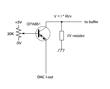
You should decouple the pot wiper voltage as the base likes to see a low impedance. Use 1k then 100 ohms from wiper to base with the midpoint grounded with a cap.
Jan
Hi Jan,
Thanks for the input. I can understand the last two, but why 1k followed by 100 ohm? Or, are you saying I should use 1k pot?
Poting
I used 0.1uf NP0/C0G with 100k resistor to the GND, and no more DC offset observed. The sound is almost as good as before, but the 1k square wave shows a tiny bit right-tilted. Could be the LF distortion caused by cap. Increasing the capacitance may help.
Your .1uf coupling cap into 100kohm is giving a -3db at 15hz, this is the tilt your seeing at 1k. You need to either increase the coupling cap to say .33uf or more.
Cheers George
Last edited:
- Status
- This old topic is closed. If you want to reopen this topic, contact a moderator using the "Report Post" button.
- Home
- Source & Line
- Digital Source
- OPA861 for I/V