anyone has Kandy's circuit diagram or knows/ could measure the secondaries please?
The toroid is faulty and there is no way to see any specs on it. Roksan would charge 65 quid + postage for a replacement one and of course is not willing to reveal the specifications!
It looks like a 50VA toroid with 15-0-15 (probably) for opamp, X-0-X, and two other windings...
The toroid is faulty and there is no way to see any specs on it. Roksan would charge 65 quid + postage for a replacement one and of course is not willing to reveal the specifications!
It looks like a 50VA toroid with 15-0-15 (probably) for opamp, X-0-X, and two other windings...
Attachments
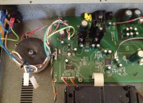
The voltage of each winding is proportional to its number of turns. Since you know the primary winding voltage you can work out the voltage of the others by counting the turns of each. It's quite time consuming though, I wouldn't bother unless you have a plan to replace it, I think a custom transformer will cost more than £65.
so I did it ") it took 2h to count all the secondaries:
it took 2h to count all the secondaries:
for opamp:
- 106 + 96 turns (d 0.65mm)
the rest:
- 46 turns (d 0.23mm)
- 81 turns (d 0.71mm)
- 142 + 134 (d 0.23mm)
Now the question is how to understand what should be the voltages and current? Suppose for opamp it would be 14v, then will it be proportional for the rest? The iron core is 40x25x15mm.
it took 2h to count all the secondaries:for opamp:
- 106 + 96 turns (d 0.65mm)
the rest:
- 46 turns (d 0.23mm)
- 81 turns (d 0.71mm)
- 142 + 134 (d 0.23mm)
Now the question is how to understand what should be the voltages and current? Suppose for opamp it would be 14v, then will it be proportional for the rest? The iron core is 40x25x15mm.
- Status
- This old topic is closed. If you want to reopen this topic, contact a moderator using the "Report Post" button.
- Home
- Source & Line
- Digital Source
- Roksan Kandy KC1 MK3 faulty toroid