Howdy
With a lot of help and guidance from "Greg from Mississippi" I've begun exploring the digital section of my ESI Juli@ XTe card (PICe version) with a view to (1) soldering a direct connection to an RCA jack for S/PDIF Out (done), (2) powering the card independently of the motherboard, (3) upgrading the clocks and (4) possible other upgrades. I'm wondering if anyone here has modified the digital side of the XTe version of this card.
I've done quite a lot of work tracing most of the key parts and voltages on this card. In many ways it is similar to the older PCI card but in others it's different. The card draws both 12V and 3.3V from the motherboard. -12V is produced on the digital section of the card but appears to only be used on the analogue part of the card. In addition, 5V (DVCC) is generated from the 12V (UA9). It too is passed to the analogue portion of the card. Annoyingly, the 5V appears to be used by UA7 on side A of the digital part of the card (and also for the optical out which I care less about). Were it not for this, I'd probably try disconnecting the 12V completely. Lastly, 1.8V is generated from the 3.3V (UA8).
Here's a couple of pics of the card with my notations. Directly beneath each is a download link to a high-resolution version of the same image. The last link is a high-resolution version of side A of the card which shows the traces more clearly.
Side B
High-res image
Side A
High-res image
Side A traces
For the clock upgrade, I am likely going to use one of Fidelity Audio's micro clocks
Fidelity Audio : C3 Low Jitter Premium clock Micro clock 2 dual output for squeezeboxes
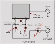
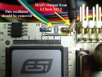
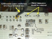
The pictures above mark the capacitors and resistors which need to be removed along with each oscillator (Y1 and Y2). Each of the oscillators has an output voltage of 1.4V (although on one end of my Y1 oscillator was measuring 1.3V).
I've also marked the points on side B of the card for direct wiring for S/PDIF out in order to avoid the breakout cable.
I suspect the best entry points for direct power is intervention via the riser cable.
Anyone else looked at this card in detail? I'm a novice and would appreciate any pointers!
Regards
Steve
With a lot of help and guidance from "Greg from Mississippi" I've begun exploring the digital section of my ESI Juli@ XTe card (PICe version) with a view to (1) soldering a direct connection to an RCA jack for S/PDIF Out (done), (2) powering the card independently of the motherboard, (3) upgrading the clocks and (4) possible other upgrades. I'm wondering if anyone here has modified the digital side of the XTe version of this card.
I've done quite a lot of work tracing most of the key parts and voltages on this card. In many ways it is similar to the older PCI card but in others it's different. The card draws both 12V and 3.3V from the motherboard. -12V is produced on the digital section of the card but appears to only be used on the analogue part of the card. In addition, 5V (DVCC) is generated from the 12V (UA9). It too is passed to the analogue portion of the card. Annoyingly, the 5V appears to be used by UA7 on side A of the digital part of the card (and also for the optical out which I care less about). Were it not for this, I'd probably try disconnecting the 12V completely. Lastly, 1.8V is generated from the 3.3V (UA8).
Here's a couple of pics of the card with my notations. Directly beneath each is a download link to a high-resolution version of the same image. The last link is a high-resolution version of side A of the card which shows the traces more clearly.
Side B
An externally hosted image should be here but it was not working when we last tested it.
High-res image
Side A
An externally hosted image should be here but it was not working when we last tested it.
High-res image
Side A traces
For the clock upgrade, I am likely going to use one of Fidelity Audio's micro clocks
Fidelity Audio : C3 Low Jitter Premium clock Micro clock 2 dual output for squeezeboxes
The pictures above mark the capacitors and resistors which need to be removed along with each oscillator (Y1 and Y2). Each of the oscillators has an output voltage of 1.4V (although on one end of my Y1 oscillator was measuring 1.3V).
I've also marked the points on side B of the card for direct wiring for S/PDIF out in order to avoid the breakout cable.
I suspect the best entry points for direct power is intervention via the riser cable.
Anyone else looked at this card in detail? I'm a novice and would appreciate any pointers!
Regards
Steve
Last edited:
Hello SGK,
How is you project going?
I about to purchase a Juli@ Xte and modify it to use the MIDI IO connections directly to chassi jacks by soldering wires. Do you know if the pins are accessible on the bottom side of the PCB at the breakout connector?
I've searched a while for a PCIe card with MIDI, ASIO2 and balanced output. I hope ESI will work for me.
Regards
Holger, Sweden
I haven't made a lot of progress to be honest. I'm not at all an electronics expert. With help from Greg in Mississippi I soldered a direct connection to a 75 Ohm RCA socket from the part marked HanRun. I have marked some of the terminals on the underside of EXT I/O but I was only tracing for S/PDIF.
SGK & Nige2000,
Steve, I'm planning to highjack your thread to become a collector for info on the Juli@ mods that I'm doing in preparation for implementing my Soekris DAC.
Nige, I sent you an email pointing to this thread.
And since Steve did such a great job documenting the XTe version here and most people wanting to mod the Juli@ anymore will likely do the XTe, it makes sense to start here and also explore how to hop-up the XTe.
I'll be honest, I will probably be a bit slow posting here for a bit as my first priority is getting the Juli@ modified & the DAM DAC running. I will take more pix this time than I did before and also document the card the way Steve did in his pix... what tool did you use for that? Full Acrobat?
Does that sound like a plan?
Later (gathering Juli@ mod parts tonight).
Greg in Mississippi
Sounds like a plan!
Nige2000 I will see if I have a pic else try to find the time to take one. Removal of the capacitors and resistors was easy (see the photos) but removing the oscillators themselves was a $%^^&. I botched it and lifted a trace which required some repair work. The clock I used is this one here: Fidelity Audio Micro Clock 2. It's not much bigger than the Envy Audio controller (see part with ESI sticker) and is affixed to the top of it. The clock has on-board regulation - I feed it regulated 12V.
Nige2000 I will see if I have a pic else try to find the time to take one. Removal of the capacitors and resistors was easy (see the photos) but removing the oscillators themselves was a $%^^&. I botched it and lifted a trace which required some repair work. The clock I used is this one here: Fidelity Audio Micro Clock 2. It's not much bigger than the Envy Audio controller (see part with ESI sticker) and is affixed to the top of it. The clock has on-board regulation - I feed it regulated 12V.
Some background on my journey with the Juli@...
I started using the Julia when I built up a cMP/cPlay system a few years back. After some light cap-upgrade mods and some linear supplies on the computer side, I decided to try some more extensive mods to the Juli@. Upgrading the four main regulators on the digital and analog cards to Dexa made a worthwhile, but not large difference. Building up a set of +5v & +-12v linear supplies, that was huge.
I ran it that way for a bit over a year, then started experimenting with various add-on DAC cards to replace the Juli@ analog card. First some AK4397 & AK4399 cards from Ric Schultz of EVS, then a TP Buffalo-32S that I built up for a friend, and finally an ES9022-based card from EUVL on this forum. All were nice upgrades, but I still say that the base Juli@ analog card with upgraded regs, seperate linear power, and some minor cap subs sounds pretty darned good, much better than it has any right to.
As I got back into DIY & mods and became more familiar with digital circuits, I realized that I could possibly obtain better results with the Juli@ if I followed some simple guidelines:
1. Keep all add-ons, upgrades, and connections very close to the associated part(s) with the shortest connection possible... millimeters matter here!
2. Parts appropriate for analog circuit upgrades are not necessarily the best for digital circuit upgrades.
3. Significant gains are available by reducing noise caused by the processing in the digital chips.
4. Mechanical regidity and vibration control makes a difference here too.
5. The only good power supply is a great power supply. Never skimp here.
I had done only a little SMD component work up to that point and realized I'd do a lot more on these mods. And as I shared with Nige, the reason I never wrote them up was that they require some delicate SMD component removal and soldering.
Yet the gains were very much worth it. I went through 3 iterations of this set of Juli@ mods... in the first round, I added the modified Dexa regulator stack along with some added filtering before and after and large ceramic filtering caps at almost all of the chip's power feed inputs. The improvement in both bass power and dynamics were very large, but even after 3-4 weeks to allow for capacitor break-in, it never lost that 'ceramic capacitor' harshness in the mids and highs. Weird that this came through on all-digital mods, but it was marked.
In my second round, I kept the modified Dexa stack and pre-post regulator filtering, but replaced all of the ceramic filtering caps at the chip feeds with Oscons. This iteration also exhibited improvements in bass and dynamics, though not to the extent of the first iteration. But the mids and highs, after about a week of break-in, were oh-so-sweet. This suggested that part selection for the location was key.
For my third round, I first went a little farther on modifying the Dexa regulators (based on a suggestion from Ric Schultz), much farther on the pre-post regulator filtering, went back to the ceramic bypass caps on all of the deeply-digital chips (memory, FPGA controller, PCI interface, etc) while using a combination of Oscon and PPS film SMD caps for the regulators and the audio interface chip (AK4114). I also modified my I2S feed to the then EUVL ES9022 card to minimize the connection length. And this iteration brought the best of the first two iterations together.
More later.
Greg in Mississippi
Last edited:
Sounds like a plan!
Nige2000 I will see if I have a pic else try to find the time to take one. Removal of the capacitors and resistors was easy (see the photos) but removing the oscillators themselves was a $%^^&. I botched it and lifted a trace which required some repair work. The clock I used is this one here: Fidelity Audio Micro Clock 2. It's not much bigger than the Envy Audio controller (see part with ESI sticker) and is affixed to the top of it. The clock has on-board regulation - I feed it regulated 12V.
Steve
Did u have to remove the crystals cap resistors etc
Just wondering because I thought I read somewhere about juila taking an external clock input in a unmod type way
How do you work clock select ?
Cheers
Nige
Nige,
Not Steve, he can provide more details (and pix I hope) on his mod... but some answers.
There are a couple of caps on each clock... C4-C7 in toto. You remove them and the clocks and can feed the clock signals in. If you want, you can upgrade one or the other of the clocks and leave one alone, if you use that sampling rate family most of the time.
Both clocks are active all of the time, AFAIK. One, the 24.5760Mhz one, is used by the Envy chip as it's internal clock. The Envy chip MIGHT power the other down and up as needed, but I doubt it... and it works ok with a full-time on 22Mhz clock.
The Fidelity Audio Micro Clock is a neat little device with two good, but not great upgrade clocks (def not at the level of the NDK or Crystek). I have one of the previous versions without the good onboard regulation, but have never taken the time to install it. They say it was developed for the Squeezebox Touch, but works on the Juli@ just as well.
Attached are some pix from one of the Juli@ mod threads on the Asylum showing some of the details.
Later!
Greg in Mississippi
Attachments
Nige, the second graphic in the first post shows which caps and resistors need removing for the XTe version of the card (I think Greg's pics are for an earlier version). I struggled removing the crystals themselves and cocked it up. It required some repair work including the wire to the Xlink CPLD. Here's a pick of the Microclock 2 sitting in place:
Greg, you did a good job removing your crystals. Any tips for this?
An externally hosted image should be here but it was not working when we last tested it.
Greg, you did a good job removing your crystals. Any tips for this?
Last edited:
SGK & Nige,
I haven't removed crystals, what I posted was from another Asylum inmate from Russia who had done that mod.
I have a couple of Juli@ I can play with... I will try a couple of ways to remove the crystals one night this week and report back.
And good work on doing the crystal mod on your XTe... and recovering from the removal issue.
Nige, yes, both crystals are active at the same time.
Greg in Mississippi
With clocks and all digital signals its not just having a return path, a critical part of signal integrity, EMC and noise control is WHERE that return path is in relation to the signal... for clocks it want to be next to it either as twisted pair or miniature coax cable anything else is bad for the signal etc.....
With clocks and all digital signals its not just having a return path, a critical part of signal integrity, EMC and noise control is WHERE that return path is in relation to the signal... for clocks it want to be next to it either as twisted pair or miniature coax cable anything else is bad for the signal etc.....
thought it was something like that......
- Status
- This old topic is closed. If you want to reopen this topic, contact a moderator using the "Report Post" button.
- Home
- Source & Line
- Digital Source
- Tweaking an ESI Juli@ XTe card