I'd like to thank Nino for trying to improve the product. I would also like to try the capacitor mod to see if a difference can be heard. It may not solve a problem but it might sound different.
If some one wants to solve a real problem lets get the remote to work on the display.")
If some one wants to solve a real problem lets get the remote to work on the display.
There is no problem!I'd like to thank Nino for trying to improve the product. I would also like to try the capacitor mod to see if a difference can be heard. It may not solve a problem but it might sound different.
How do you think to hear the difference which can not be measured?
Difference can not be measured..The cap is questionable but it might sound different. I still have to try it.
Maybe you can hear something that can not be measured..
Is there any DIY DAC with remote?no remote = real problem.
I can't wait to see some Nino's original design..Nino is obviously very convinced and I can appreciate that.
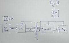
I like the concept of reclocking the i2s output from the XMOS after galvanic isolating it. But it doesn't work in this design unfortunately.
Ninon, I appreciate your contribution to this thread. Can I ask, did you feel there was a weakness with this design, based on not being audibly insensitive to transport/cables, then came up with a hypothesis for a cause?
Difference can not be measured..
Maybe you can hear something that can not be measured..
Sure, all the time.
Much of the time tradition measurements fall short of revealing factors that our ear/brain are very sensitive to.
So I use the most sensitive and sophisticated measurement tools I have: my two ears! They also happen to be the end transducers for which all this stuff is intended.
No we can measure far more than we can hear... to say any different is avoiding the truth. What we cant measure is perception and this is what fools us a lot of the time. But this is advantageous for the flubby side of the hobby where views are based on hearsay and word of mouth with no empirical data or measurements to back up views. Now in the digital side of things measurements are critical to what is going on in the digital realm, especially if you want the best in terms of signal integrity (this is not a super fast rise time as many think, but the correct rise time for the base frequency the slower rise time the better from a SIV point of view ) and minimum EMC.
The real-time, synchronously operating nature of the XMOS architecture isn't fully utilized for reliable audio processing by using the 26 MHz reference clock IMO.
As explained in my previous post the audio MCK, being referred to as 'application clock' in the second document, is sampled using the XCore clock of the device. By being derived of / locked to the 26MHz clock, the XCore clock isn't closely related to the audio clock.
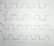
What this means in terms of timing I tried to illustrate in first picture. The top 2 signals shows the sampling of a clock signal with a rate exactly 3 times (for XMOS 1 bit port the number would be ~20 times). Although the edge is not as steep as the original, timing is still in tact because a slaved device is edge driven. The 2 signals at the bottom show sampling a non-related clock. The slaved device still being edge driven, will be subject to a deteriorated clock.
Conclusion would be that clock phase isn't a problem, as long as both clocks are related integrity is preserved. To describe this relation: Both the sampled and the sampling clock should have the same highest prime number divider in common. For 22.579 MHz audio clock prime numbers are 2,3,5,7, for 24.576 MHz audio clock 2,3,5 , for 26.0 MHz clock this is 2,5,13. (so XCore frequency can't be generated with higher prime number division than highest prime of respective audio clock either, the number 5)
IMO best would be to slave the XMOS device to the master audio clock, just like the reclocker and DAC. This way the XMOS reference clock is related to the audio clock, and can either be used directly to generate i2s in the audio driver thread, or to acquire the audio clock like the current procedure. Experiments should decide what's best.
As a bonus the PLL of the device will reject the added jitter to the audio clock by the isolator (provided the PLL_AVDD pin is powered separately). Switching back and forth to both clock families would also mean the XMOS device / PLL need to be reset to the new clock, complicating switching a bit, but I expect that shouldn't be a problem. Further on, the reclocker will correct the jitter added to the i2s and sp/dif by the isolator, just as joro intended.
The USB transciever is still clocked by the 26MHz clock. The incoming ULPI will be sampled by the XMOS device on 8 bit port, with the same effect as described. But this time the effect isn't a problem, because at this stage of the transmission it's about data, not timed data; Here jitter of this level isn't a problem for data integrity.
Nino
As explained in my previous post the audio MCK, being referred to as 'application clock' in the second document, is sampled using the XCore clock of the device. By being derived of / locked to the 26MHz clock, the XCore clock isn't closely related to the audio clock.
What this means in terms of timing I tried to illustrate in first picture. The top 2 signals shows the sampling of a clock signal with a rate exactly 3 times (for XMOS 1 bit port the number would be ~20 times). Although the edge is not as steep as the original, timing is still in tact because a slaved device is edge driven. The 2 signals at the bottom show sampling a non-related clock. The slaved device still being edge driven, will be subject to a deteriorated clock.
Conclusion would be that clock phase isn't a problem, as long as both clocks are related integrity is preserved. To describe this relation: Both the sampled and the sampling clock should have the same highest prime number divider in common. For 22.579 MHz audio clock prime numbers are 2,3,5,7, for 24.576 MHz audio clock 2,3,5 , for 26.0 MHz clock this is 2,5,13. (so XCore frequency can't be generated with higher prime number division than highest prime of respective audio clock either, the number 5)
IMO best would be to slave the XMOS device to the master audio clock, just like the reclocker and DAC. This way the XMOS reference clock is related to the audio clock, and can either be used directly to generate i2s in the audio driver thread, or to acquire the audio clock like the current procedure. Experiments should decide what's best.
As a bonus the PLL of the device will reject the added jitter to the audio clock by the isolator (provided the PLL_AVDD pin is powered separately). Switching back and forth to both clock families would also mean the XMOS device / PLL need to be reset to the new clock, complicating switching a bit, but I expect that shouldn't be a problem. Further on, the reclocker will correct the jitter added to the i2s and sp/dif by the isolator, just as joro intended.
The USB transciever is still clocked by the 26MHz clock. The incoming ULPI will be sampled by the XMOS device on 8 bit port, with the same effect as described. But this time the effect isn't a problem, because at this stage of the transmission it's about data, not timed data; Here jitter of this level isn't a problem for data integrity.
Nino
Attachments
Last edited:
Sorry, I messed up with the prime numbers. In order to have an accurate sampling of the incoming audio clock, the sampling frequency must be an integer multiplication of that clock frequency number.
For 22.5792 MHz this would be a factor 22 (496.7424 MHz XCore) and for 24.5760 MHz this would be a factor 20 (491.5200 MHz XCore).
For 22.5792 MHz this would be a factor 22 (496.7424 MHz XCore) and for 24.5760 MHz this would be a factor 20 (491.5200 MHz XCore).
Last edited:
One question for Vulejov.
You published output schematic that suits best for you. I have made some other things in last time but yesterday when I look clossely to both boards ...dac and output board, you just published schematic and put filter simulation for output board...but i see that on dac board it is first part of filter ...5100R and unknown capacitor then goes to output board wih your schematic...so it is 3rd order filter not 2nd order....am I wrong?
You published output schematic that suits best for you. I have made some other things in last time but yesterday when I look clossely to both boards ...dac and output board, you just published schematic and put filter simulation for output board...but i see that on dac board it is first part of filter ...5100R and unknown capacitor then goes to output board wih your schematic...so it is 3rd order filter not 2nd order....am I wrong?
I use now output board on schematic..
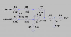
With 5k1 and unknown C16-C22 on DAC board it forms 2nd order filter..
Maybe there is space to change 5k6 with 6k8-7k5 and 680p with 220p-470p..
http://jlsounds.com/uploads/LME49710_schematic.pdf
With 5k1 and unknown C16-C22 on DAC board it forms 2nd order filter..
Maybe there is space to change 5k6 with 6k8-7k5 and 680p with 220p-470p..
http://jlsounds.com/uploads/LME49710_schematic.pdf
Attachments
I am a beginner DIYer. I'm riding the combo I2S over AK4490 + USB + 49710 LME.
I think I need help
I looked assembly, and I saw:

The A 5V board has the jumpers installed
The B 5V board does'nt have the jumpers installed
Is correct?
Why ? (Both entries of AK44490 board have written same voltage: 5V)
Thanks!
I think I need help
I looked assembly, and I saw:
The A 5V board has the jumpers installed
The B 5V board does'nt have the jumpers installed
Is correct?
Why ? (Both entries of AK44490 board have written same voltage: 5V)
Thanks!
With jumpers installed output voltage is 4V, supply USB input part..
Without jumpers output voltage is 5V.. supply reclock, oscillators and DAC..
http://jlsounds.com/uploads/Specifications.pdf
http://jlsounds.com/uploads/AK4490_board.pdf
http://jlsounds.com/uploads/Power_Supply.pdf
Without jumpers output voltage is 5V.. supply reclock, oscillators and DAC..
http://jlsounds.com/uploads/Specifications.pdf
http://jlsounds.com/uploads/AK4490_board.pdf
http://jlsounds.com/uploads/Power_Supply.pdf
Capacitors 330p....but i see that on dac board it is first part of filter ...5100R and unknown capacitor
Resistors 510R..
Thank you. So in original sheme 3rd order.
What was the influence in sound when you start to remove capacitors...?
When i replaced opamp in Buffalo 3 ivy3 output with LME49990 without capacitor i get huge oscillation, with lme49720 not, so remove caps and try various opamps without measurement is not a good idea.
In my small china ak4490dac, i couldn*t enjoy with lme49990 but in big ak4490 high quality dac LME49990 sings beautifull. After number of trying... i must loaded lm317 /337 with 30-40mA load and instead 2200pf used 2860pf. Annoying thin high frequency was gone. Relaxed detailed sound is now also with lme49990.
Opamps need optimization to sing well.
I tried lt1364 similar to your favoruite choice, is nice for me too soft similar ad827, lme49990 is very neutral and gives you some magic in music. Also opa627 is good opa827 too bright, Lme49720 to bright and not refined similar lm4562 and opa1642, ad797 oscillated a bit, opa1612/11 to soft and midrange is uninteresting. Laid back.
That's wright.. but first filter on AK4490 board is very high..Thank you. So in original sheme 3rd order.
What was the influence in sound when you start to remove capacitors...?
I only remove 150p capacitor from original schematic, I think that kind of filter slowing down opamp..
I can't hear difference between AD797 and LT1363, both are clearly better than LME49710..
Thanks Vulejov.
I have built the set and really sounds fine
Which one..
- Status
- This old topic is closed. If you want to reopen this topic, contact a moderator using the "Report Post" button.
- Home
- Source & Line
- Digital Line Level
- XMOS DSD 384 kHz / 32bit USB