Hi All (and hopefully Scott is reading, too!!),
well, I have just finished my DACKit and have fired it up using a 12v 7.5 ah gel battery. The batt had 11.5V when we started.
I was sad to hear lots of fuzz, and the music very quiet in the background. Our houseguest re-connected everything and turned on the system again when I was out of the room. Much excitement as music filled the room! Hurrah!
Anyway, I left the CD on overnight to burn the dac in. This morning, the fuzz was back. Hmm.
However, the batt voltage was down at 6.5!!! I recharged it today, and it was steady at 13-ish. OK, now to re-connect.
Still fuzz, then I remembered something about the order of when to switch on the source and the dac. I had the CD on and then powered up the dac. It worked !
Happy that I thought I had solved the problem, we listened to some Annie Lennox (Album Bare, track 5 "Wonderful"). No problem here, sounded very nice. Then, only occasionally, the sound would drop out. Once the loud part of the song kicked in, the system went dead. Hmm. 
I turned everything off, back on, and the fuzz had returned.
Does anyone have any ideas? I was as careful as I could when I assembled the dac, but I think I have missed something here.....
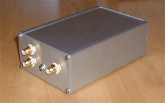
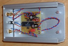
Anyway, here are some pics. This is my first project, and it will not be complete until I can enjoy those sounds.
BTW, compenents are 0.1% resistors, BG and Wima caps, teflon coated silver wire etc etc.
CHEERS
Jon
well, I have just finished my DACKit and have fired it up using a 12v 7.5 ah gel battery. The batt had 11.5V when we started.
I was sad to hear lots of fuzz, and the music very quiet in the background. Our houseguest re-connected everything and turned on the system again when I was out of the room. Much excitement as music filled the room! Hurrah!
Anyway, I left the CD on overnight to burn the dac in. This morning, the fuzz was back. Hmm.
However, the batt voltage was down at 6.5!!!
I recharged it today, and it was steady at 13-ish. OK, now to re-connect.Still fuzz, then I remembered something about the order of when to switch on the source and the dac. I had the CD on and then powered up the dac. It worked
!Happy that I thought I had solved the problem, we listened to some Annie Lennox (Album Bare, track 5 "Wonderful"). No problem here, sounded very nice. Then, only occasionally, the sound would drop out.
Once the loud part of the song kicked in, the system went dead. Hmm. I turned everything off, back on, and the fuzz had returned.
Does anyone have any ideas? I was as careful as I could when I assembled the dac, but I think I have missed something here.....
Anyway, here are some pics. This is my first project, and it will not be complete until I can enjoy those sounds.
BTW, compenents are 0.1% resistors, BG and Wima caps, teflon coated silver wire etc etc.
CHEERS
Jon
Attachments
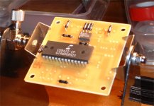
Are you sure you soldered the electrolyics in the right way ?? I don't see that you made errors with grounding but it is not always clear what one sees on a picture. to my eyes the DAC looks OK.
Did you double-check the resistor values and did you measure as well ? Did you doublecheck solder joints ? Did you measure the voltages at the DAC chip and receiver ? I had once trouble with dropouts caused by too large film caps at the input of the CS8412 receiver. I also read once that a forum member used the 7808/9 for the receiver and the 7805 for the DAC chip ...
Maybe it is wise to mail Scott himself for support !?!?! Although I never bought anything from him he always helped me with things I wanted to know.
Hi JP,
I will check all the joints etc. The resistors have the values written on them, so I did not bother to measure them. However, I have not checked the voltages at the dac and receiver. I have a multimeter, so I'll give it a go tomorrow.
The film cap sizes are within the ranges specified, but I was experiencing drop-out, so I will have another look at them.
I soldered in the electros with the short leg as negative. Some were NP, but the polar ones had a gold "-" vertically on the side.
I'm glad you think it looks ok though - I'm really pleased with it (apart from the glitches!!)
Thanks for your thoughts!!
Jon
Missing LEDs
I forgot to mention that the LEDs are not installed as I coudn't make up my mind which one to specify.
Of course I want blue but when I look at the LEDs available and work out the 330R resistors into the equasion in the Maplin cataloge, the figires don't quite add up (or I will get a very soft blue???).
I am learning tons as I am going thought this!!
Jon
I forgot to mention that the LEDs are not installed as I coudn't make up my mind which one to specify.
Of course I want blue
but when I look at the LEDs available and work out the 330R resistors into the equasion in the Maplin cataloge, the figires don't quite add up (or I will get a very soft blue???).I am learning tons as I am going thought this!!
Jon
Jon, please check current draw of those fancy blue LED's first ! Not being one with much experience with blue LED's ( it is more original to use plain read and green ones nowadays with every pc or amp having blue LED's )
I recall they have a Uf of 4V and draw more current than their red/yellow/green/orange collegues. AFAIK the LED's on DACkit are fed directly from the CS8412 that has a current limit. Please check CS8412's datasheet for that value. You might have a chance that a switching transistor has to be added.
I leave the googling for the blue LED current draw and the maximum current output of the CS8412 for you.
The series resistance is calculated as follows: R = ( Ubat - Uf ) / I led. I led is the desired current through the LED of course. Ubat is 5V and Uf is the forward voltage of the LED in question and depends on the colour of the LED.
Still waiting for fancy purple LED's ....
)I recall they have a Uf of 4V and draw more current than their red/yellow/green/orange collegues. AFAIK the LED's on DACkit are fed directly from the CS8412 that has a current limit. Please check CS8412's datasheet for that value. You might have a chance that a switching transistor has to be added.
I leave the googling for the blue LED current draw and the maximum current output of the CS8412 for you.
The series resistance is calculated as follows: R = ( Ubat - Uf ) / I led. I led is the desired current through the LED of course. Ubat is 5V and Uf is the forward voltage of the LED in question and depends on the colour of the LED.
Still waiting for fancy purple LED's ....
Pretty work Jon!
fuzzy frizzy huh? Double check PLL filter values, 1k and 0.047 should work for sure. Then shorten and untwist and separate the input lead to the receiver. If you need the length, use a miniature 75 ohm coax, but it's bad form to twist that pair. Good lookin' dac there, I'd say.
fuzzy frizzy huh? Double check PLL filter values, 1k and 0.047 should work for sure. Then shorten and untwist and separate the input lead to the receiver. If you need the length, use a miniature 75 ohm coax, but it's bad form to twist that pair. Good lookin' dac there, I'd say.
 !!).
!!).Don't know if the PCB permits it without having to drill new holes but turning the board a quarter to the right maybe will solve the too long digital cable crossing the supplylines ( I would shorten them anyhow ). You will have to change the SPDIF and the powerconnector if you do this. So SPDIF will be in the middle if you understand what I mean.
I always use thin 75 Ohm coax for the input. Less possible problems and electrically more correct. It is called RG-175 ( 3 mm diameter and flexible ).
Reroute the supplylines at the opposite side of the digital input just as Scott suggested.
A last tip: do a search here for the Monkeysect filter. Your DAC will sound even better.
Have fun with your DAC !
Some results:
Hi JP, Scott,
I have done some measurments and have some (unexpected) results.
Battery voltage = 12.88
Input at the L7808CV = 12.85
Output from L7808CV = 9.94 (yup, 9.94!!)
Voltage across 1543 pins 5/4 = 9.94
Input at the L78S05CV = 12.83
Output from L78S05CV = 4.98
CS8412 at pins 7 and 22 = 4.98
I have no digital source with me to do any further measurments or tests. I suspect that my IC regulator is not doing the business (by nearly 2 volts)!!
I am going to order some RG175 from Farnell, and will replace the 8v ic. Do you have any recommendations - i.e. performance wise?? It appears that the 5v part is behaving itself. If I have damaged the TDA (max 8v) then I have a spare - but I am hoping I got away with it.......
This overvoltage might explain the dropping of the signal when Annie Lennox was getting loud!!
More news as it comes........
Jon
Hi JP, Scott,
I have done some measurments and have some (unexpected) results.
Battery voltage = 12.88
Input at the L7808CV = 12.85
Output from L7808CV = 9.94 (yup, 9.94!!)
Voltage across 1543 pins 5/4 = 9.94
Input at the L78S05CV = 12.83
Output from L78S05CV = 4.98
CS8412 at pins 7 and 22 = 4.98
I have no digital source with me to do any further measurments or tests. I suspect that my IC regulator is not doing the business (by nearly 2 volts)!!
I am going to order some RG175 from Farnell, and will replace the 8v ic. Do you have any recommendations - i.e. performance wise?? It appears that the 5v part is behaving itself.
If I have damaged the TDA (max 8v) then I have a spare - but I am hoping I got away with it.......This overvoltage might explain the dropping of the signal when Annie Lennox was getting loud!!
More news as it comes........
Jon
Output from L7808CV = 9.94 (yup, 9.94!!)
Now that explains a lot ! That poor TDA must have got the fever ...
It was surely clipping. You see that measuring is the first thing to do even when things *seem* OK.
Another lesson learned!!
Hi JP,
I now appreciate that!!
I wonder if getting dodgy ICs is common?? Or is my assumption that the IC was faulty flawed? Perhaps I damaged it with prolonged heat while soldering it in.
Anyway, I'm going to look for a less replacement!!
Cheers
Jon
PS Do you mean RG-179?
Hi JP,
I now appreciate that!!
I wonder if getting dodgy ICs is common?? Or is my assumption that the IC was faulty flawed? Perhaps I damaged it with prolonged heat while soldering it in.
Anyway, I'm going to look for a less
replacement!!Cheers
Jon
PS Do you mean RG-179?
Not to be deterred...........
.........I have ordered some more VRegs (and some Pana FCs for my AMPKit pcbs, LEDs - a special variety - bezels, coax, etc!!
Just to make sure that I am not going to kill the ICs, is this ok?
To test a VReg before installation, put 12V from the battery through the input and gnd (I am thinking of taping wires, but leaving some ground exposed), and then measure gnd and output? This will be on the bench, before installation (don't want the same dodgy output voltage as before!! ).
Apart from that, this Friday is DACKit day and the weekend will have some thought towards the four LM3875 monoblocks that I am planning!!!
A little bit of knowledge is a dangerous thing....
0100.
Bed.

.........I have ordered some more VRegs (and some Pana FCs for my AMPKit pcbs, LEDs - a special variety - bezels, coax, etc!!
Just to make sure that I am not going to kill the ICs, is this ok?
To test a VReg before installation, put 12V from the battery through the input and gnd (I am thinking of taping wires, but leaving some ground exposed), and then measure gnd and output? This will be on the bench, before installation (don't want the same dodgy output voltage as before!!
).Apart from that, this Friday is DACKit day
and the weekend will have some thought towards the four LM3875 monoblocks that I am planning!!! A little bit of knowledge is a dangerous thing....
0100.
Bed.
An update.....
Hi All,
here is an update - the bottom line is that I still have mightily distorted output, at very low power.
However, I have:
tested the 8v reg - It was messing about at nearly 10v, but now, for some bizarre reason, it is steady at 8v when I measure it (and I've been measuring it lots!!).
Replaced the twisted-pair input for some 75 ohm coax (not the thin stuff that I couldn't get - mad the job a little challenging!!).
Rewired the outputs - shorter (though all equal lengths) and better routing.
Re-routed the pwr supply wires to the case wall on the output side.
Finally, I have replaced the 1543 with a spare.
Well, I had high hopes when I went into testing, but I was still in the same boat!!!
I would really appreciate any other thoughts on what the problem could be.
I think that the next stage would be to re-solder any joints on the pcb that aren't chromium bright!!
I am very pleased with the case-mods (incl feet that were originally stainless wine bottle stoppers from Sainsburys!! )
At least I am learning how to use my multimeter!!
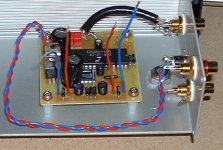
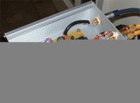
Here is a pic of the Work In Progress:
Cheers
Jon
Hi All,
here is an update - the bottom line is that I still have mightily distorted output, at very low power.
However, I have:
tested the 8v reg - It was messing about at nearly 10v, but now, for some bizarre reason, it is steady at 8v when I measure it (and I've been measuring it lots!!).
Replaced the twisted-pair input for some 75 ohm coax (not the thin stuff that I couldn't get - mad the job a little challenging!!).
Rewired the outputs - shorter (though all equal lengths) and better routing.
Re-routed the pwr supply wires to the case wall on the output side.
Finally,
I have replaced the 1543 with a spare.Well, I had high hopes when I went into testing, but I was still in the same boat!!!
I would really appreciate any other thoughts on what the problem could be.
I think that the next stage would be to re-solder any joints on the pcb that aren't chromium bright!!
I am very pleased with the case-mods (incl feet that were originally stainless wine bottle stoppers from Sainsburys!!
)At least I am learning how to use my multimeter!!
Here is a pic of the Work In Progress:
Cheers
Jon
Attachments
- Status
- This old topic is closed. If you want to reopen this topic, contact a moderator using the "Report Post" button.
- Home
- Source & Line
- Digital Source
- DACKit complete, but a few issues!!