Basically the same I/V stage as for the TDA1541 posted earlier, just some adjusted values,
Like 2 LED's for setting the output on the TDA1543 output to aprox. 2.4V
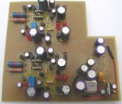
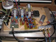
This time it's a one board solution containing:
TDA1543 with REG101-5 smd LDO regulator,
Tent XO with REG101-5 smd LDO regulator,
74VHC374 for reclocking all I2S lines; note the double reclocking which even allows one to hook up an external asynchronous clock")
3 legged pre-regulator (one choosen for lowest noise, thanks Guido)
Of course lots of RC filtering, smd bypass caps (not shown on schematic, many 220u/10V Oscon's.
The TDA1543 has a combo of 1000u/10V Rubycon ZL (best bass), 220u/10V Oscon (HF filtering, creates "peace" in sound).
The I/V part uses DALE/RIKEN for Riv, and Philips KP for Riv.
The caps for filtering the TL431 references are 10u/10V Oscon this time.
The board only needs unregulated power supplies and I2S as inputs and outputs a clock signal for my cd player and the DC coupled analog outputs.
Sound:
Well, the same improvements as with the TDA1541 folded cascode I/V; there is more depth, width, microdetail in the sound.
This sounds incredibly transparent;
I recently compared this player to the passive I/V player and the cd player with single ended common base I/V and this is another level.
It's a matter of music now whether I use this TDA1543 player or the TDA1541A-S2. The latter is great for jazz and easy listening, the TDA1543 I really prefer when things have to rock.
One happy chap
PS
I took the pictures just before I finished the boards, so I could take 'm outside in daylight. So some parts are not there yet (like the integrator cap)
PPS
Peter Daniel, how far are u with these boards
Like 2 LED's for setting the output on the TDA1543 output to aprox. 2.4V
This time it's a one board solution containing:
TDA1543 with REG101-5 smd LDO regulator,
Tent XO with REG101-5 smd LDO regulator,
74VHC374 for reclocking all I2S lines; note the double reclocking which even allows one to hook up an external asynchronous clock
3 legged pre-regulator (one choosen for lowest noise, thanks Guido)
Of course lots of RC filtering, smd bypass caps (not shown on schematic, many 220u/10V Oscon's.
The TDA1543 has a combo of 1000u/10V Rubycon ZL (best bass), 220u/10V Oscon (HF filtering, creates "peace" in sound).
The I/V part uses DALE/RIKEN for Riv, and Philips KP for Riv.
The caps for filtering the TL431 references are 10u/10V Oscon this time.
The board only needs unregulated power supplies and I2S as inputs and outputs a clock signal for my cd player and the DC coupled analog outputs.
Sound:
Well, the same improvements as with the TDA1541 folded cascode I/V; there is more depth, width, microdetail in the sound.
This sounds incredibly transparent;
I recently compared this player to the passive I/V player and the cd player with single ended common base I/V and this is another level.
It's a matter of music now whether I use this TDA1543 player or the TDA1541A-S2. The latter is great for jazz and easy listening, the TDA1543 I really prefer when things have to rock.
One happy chap
PS
I took the pictures just before I finished the boards, so I could take 'm outside in daylight. So some parts are not there yet (like the integrator cap)
PPS
Peter Daniel, how far are u with these boards
I finished the output board and I'm half way done with this board. I have a feeling that this will be the first one I'll try.
What can I use for Tent clock (if I don't have one)? I have a pretty good Raltron VCXO running at 24,704 Hz; would it work here? The other choice could be Kwak Clock, I guess, as I have one too. What are you using for smd regulators?
I see a small cap installed on servo chip. What's it for?
PS: I would've finish much earlier, but I was too busy with the amps.
IV Schematic
Hi Rudolf,
Looks nice this PCB.
Any reason why you don't use the CFB (Skizlai) in the input?
I don't see any use for current sink T5. It may present a high impedance to T6 but the IV resistor is parallel to it and is only 1k3.
In the same way I don't see any use for T11. The T6 circuit is a common base amplifier and thus presents a low input impedance.
T6 is a current source in itself. The current through T11 is already the sum of currents determined by T1 & T6. You can get a conflict of current sources and sinks in your circuit.
I don't like servos and preregulators, you already know.
You use two flip-flops in series but if you use the same clock as for the player only one is needed, as the clock is not asynchronous. Also I doubt if there is any use for reclocking in a one-box player as you don't have any data related jitter and no PLL recovered clock. My research has shown that you gain very little by using an 11.2896 MHz clock for reclocking just as reclocking the SPDIF output does not bring anything. Kusunoki the originator of the reclocking idea was using a 50 MHz clock. Still on my schedule is trying the 125 MHz clock from Vite. Sonically results are very dependent on the clock used. In my current set-up with I2S Direct I don't use any reclocker.
rbroer said:Basically the same I/V stage as for the TDA1541 posted earlier, just some adjusted values,
Like 2 LED's for setting the output on the TDA1543 output to aprox. 2.4V
This time it's a one board solution containing:
TDA1543 with REG101-5 smd LDO regulator,
Tent XO with REG101-5 smd LDO regulator,
74VHC374 for reclocking all I2S lines; note the double reclocking which even allows one to hook up an external asynchronous clock
3 legged pre-regulator (one choosen for lowest noise, thanks Guido)
Of course lots of RC filtering, smd bypass caps (not shown on schematic, many 220u/10V Oscon's.
The TDA1543 has a combo of 1000u/10V Rubycon ZL (best bass), 220u/10V Oscon (HF filtering, creates "peace" in sound).
The I/V part uses DALE/RIKEN for Riv, and Philips KP for Riv.
The caps for filtering the TL431 references are 10u/10V Oscon this time.
The board only needs unregulated power supplies and I2S as inputs and outputs a clock signal for my cd player and the DC coupled analog outputs.
Hi Rudolf,
Looks nice this PCB.
Any reason why you don't use the CFB (Skizlai) in the input?
I don't see any use for current sink T5. It may present a high impedance to T6 but the IV resistor is parallel to it and is only 1k3.
In the same way I don't see any use for T11. The T6 circuit is a common base amplifier and thus presents a low input impedance.
T6 is a current source in itself. The current through T11 is already the sum of currents determined by T1 & T6. You can get a conflict of current sources and sinks in your circuit.
I don't like servos and preregulators, you already know.
You use two flip-flops in series but if you use the same clock as for the player only one is needed, as the clock is not asynchronous. Also I doubt if there is any use for reclocking in a one-box player as you don't have any data related jitter and no PLL recovered clock. My research has shown that you gain very little by using an 11.2896 MHz clock for reclocking just as reclocking the SPDIF output does not bring anything. Kusunoki the originator of the reclocking idea was using a 50 MHz clock. Still on my schedule is trying the 125 MHz clock from Vite. Sonically results are very dependent on the clock used. In my current set-up with I2S Direct I don't use any reclocker.
Hi,
Looks very nice indeed! But I think that a CFP for the input can give a improvement. It lowers input impedance 10x.
As for the servo.. why a OPA627? You would need it's speed, it is not very quiet. Maybe the DC/drift spec are the reason? That's a very expensive servo.......
Greeting,
Thijs
Looks very nice indeed! But I think that a CFP for the input can give a improvement. It lowers input impedance 10x.
As for the servo.. why a OPA627? You would need it's speed, it is not very quiet. Maybe the DC/drift spec are the reason? That's a very expensive servo.......
Greeting,
Thijs
Re: IV Schematic

I suggest studying the circuit a bit better Elso, you're mixing up constant current sources with (folded) cascodes.
In fact, the board is layed out for CFP everywhere, but I had oscillations. Also Terry pointed out, they wouldn't sound natural. In the end I got it working with CFP, but must concur with him, somehow it doesn't sound right, natural.
About reclocking in a cd player, my experiences are quite different, it does quite a lot IMHO, especially when using a very low jitter clock like the Guido Tent XO. My preference goes to his oscillator, least veiled sound IMO, but YMMV of course
It does make sense of course, a clock feeding a decoder chip will propagate through many internal gates, not improving jitter performance at all.
I've implemented synchronous reclocking in cd players 3 times now, and each time there was a very noticable improvement, tighter bass, better PRAT
Servo works in current mode; simulations indicate no THD effect, just for the sake of it I used good resistors. I've listened with and without the servo opamp, there's no difference I can notice.
The servo is there for safety, there is some drift due to temperature changes.
I had several requests for boards for the TDA1541 output stage, and told y'all to wait till I finished fine-tuning the TDA1543 board. This has finished now, so I'll probably order some new boards soon. I'll implement a few changes and make provisions for the "super-pair" this time, replacing the CFP.
Y'all got my email, closing time two weeks from now (both pcb's).
It's just a socket with integrated decoupling cap between 8 and 4, here it won't do anything since power is on 7 and 4, but I just happened to have only these onesPeter Daniel said:I see a small cap installed on servo chip. What's it for?
T6 is NOT a current source ElsoElso Kwak said:
I suggest studying the circuit a bit better Elso, you're mixing up constant current sources with (folded) cascodes.
In fact, the board is layed out for CFP everywhere, but I had oscillations. Also Terry pointed out, they wouldn't sound natural. In the end I got it working with CFP, but must concur with him, somehow it doesn't sound right, natural.
About reclocking in a cd player, my experiences are quite different, it does quite a lot IMHO, especially when using a very low jitter clock like the Guido Tent XO. My preference goes to his oscillator, least veiled sound IMO, but YMMV of course
It does make sense of course, a clock feeding a decoder chip will propagate through many internal gates, not improving jitter performance at all.
I've implemented synchronous reclocking in cd players 3 times now, and each time there was a very noticable improvement, tighter bass, better PRAT
Servo works in current mode; simulations indicate no THD effect, just for the sake of it I used good resistors. I've listened with and without the servo opamp, there's no difference I can notice.
The servo is there for safety, there is some drift due to temperature changes.
I had several requests for boards for the TDA1541 output stage, and told y'all to wait till I finished fine-tuning the TDA1543 board. This has finished now, so I'll probably order some new boards soon. I'll implement a few changes and make provisions for the "super-pair" this time, replacing the CFP.
Y'all got my email, closing time two weeks from now (both pcb's).
Re: Re: IV Schematic
I beg your pardon, Rudolf, you take me for dumb?
I posted even a similar circuit with CFB input on 07-05-2003:
http://www.diyaudio.com/forums/showthread.php?postid=201512#post201512

rbroer said:
T6 is NOT a current source Elso
I suggest studying the circuit a bit better Elso, you're mixing up constant current sources with (folded) cascodes.
In fact, the board is layed out for CFP everywhere, but I had oscillations. Also Terry pointed out, they wouldn't sound natural. In the end I got it working with CFP, but must concur with him, somehow it doesn't sound right, natural.
About reclocking in a cd player, my experiences are quite different, it does quite a lot IMHO, especially when using a very low jitter clock like the Guido Tent XO. My preference goes to his oscillator, least veiled sound IMO, but YMMV of course
It does make sense of course, a clock feeding a decoder chip will propagate through many internal gates, not improving jitter performance at all.
I've implemented synchronous reclocking in cd players 3 times now, and each time there was a very noticable improvement, tighter bass, better PRAT
Servo works in current mode; simulations indicate no THD effect, just for the sake of it I used good resistors. I've listened with and without the servo opamp, there's no difference I can notice.
The servo is there for safety, there is some drift due to temperature changes.
I had several requests for boards for the TDA1541 output stage, and told y'all to wait till I finished fine-tuning the TDA1543 board. This has finished now, so I'll probably order some new boards soon. I'll implement a few changes and make provisions for the "super-pair" this time, replacing the CFP.
Y'all got my email, closing time two weeks from now (both pcb's).
I beg your pardon, Rudolf, you take me for dumb?
I posted even a similar circuit with CFB input on 07-05-2003:
http://www.diyaudio.com/forums/showthread.php?postid=201512#post201512
Attachments
No, Elso, I don't think you're dumb
Here's a more readable schematic, basically the electronic circuit posted earlier.
Current sink T1 sets the bias current through T8,
Current sink T5 sets the bias current through T6,
Current source (T11) provides:
(1) current required by current sink T1
(2) current required by current sink T5
(3) zero level bias current (sinking) for TDA1543, typically 50% full scale, 1.15mA
Any "left-over" DC current can only go through the Riv.
Hence the current sinks is adjusted for zero DC flow through Riv, ergo 0 Vdc offset over it.
Since there are some thermal effects, the DC servo slowly sources or sinks a tiny adjustment current at the DAC, to keep 0 Vdc at the output, it's influence is limited to about +/-100uA
Now I'm not gonna argue with you Elso about "your designs" being better, I'm sure they are
This works great for me, never had such a great sound from my cd players. In the end, that's what I care about.
Attachments
Next Version
In the next (and final) version I will add the "super-pair" as suggested by JCOX. Might as well give it a try, like I did for the CFP on my current boards.
If you look at the photo, you seen some unused places for transistors and SMD resistor for the CFP.
Will post my findings in due time when I receive some new pcb's.
Happy DIY.
In the next (and final
) version I will add the "super-pair" as suggested by JCOX. Might as well give it a try, like I did for the CFP on my current boards.If you look at the photo, you seen some unused places for transistors and SMD resistor for the CFP.
Will post my findings in due time when I receive some new pcb's.
Happy DIY.
Attachments
BTW,
If your amplifier already has an input capacitor, and you're implementing the folded cascode I/V circuit,
I suggest leaving the DC servo out and adjusting the DC level on Riv a few volts negative, to create some bias voltage for these input coupling caps. VCE(T6) increases as well, which is a good thing.
Re: Next Version
Thank you rbroer,
there is a lot of interesting stuff in your posts...
BTW can you explain me the abbreviations CFP and YMMV ?
Thanks
rbroer said:Happy DIY.
Thank you rbroer,
there is a lot of interesting stuff in your posts...
BTW can you explain me the abbreviations CFP and YMMV ?
Thanks
Re: Next Version
I think that Elso was telling that his design is better without Q4 than with it. He wasn't telling his design is better than yours
rbroer said:out +/-100uA
Now I'm not gonna argue with you Elso about "your designs" being better, I'm sure they are
I think that Elso was telling that his design is better without Q4 than with it. He wasn't telling his design is better than yours
Re: Re: Next Version
-Right-Bricolo said:
I think that Elso was telling that his design is better without Q4 than with it. He wasn't telling his design is better than yours
Hi rbroer
I don't understand this configuration. Is their a ealier post somewhere that expleains it, or maybe could you elaborate a bit?
Regards,
Thijs
"super-pair" as suggested by JCOX
I don't understand this configuration. Is their a ealier post somewhere that expleains it, or maybe could you elaborate a bit?
Regards,
Thijs
Comparing with the Rudolf’s previous version, actually nothing has changed but that folding is added – and both Rudolf and Vuki are reporting an improvement. What I found as an interesting difference spicing these circuits is that the current through the T11 is now more constant, with 4mA p-p signal current it varies +/-1uA instead of the previous +/-50uA. Spice also shows the harmonic distortion is 2.5 times (9dB) less in this case (all else being equal), but this last circuit can be significantly improved if runs at higher currents.
Elso, your last suggestion is really funny, I checked it too (put the plain resistor instead of the T11) and guess what… A lot of it again depends on biasing but the total distortion level went down for 2.4 times and general rule is: the second harmonic goes notably lower and the third harmonic slightly rises.
Pedja
So, I have finally built it.
Had some small problems, but eventually it's working. There is a mistake in a first drawing: DATA should go to pin 7 and BCK to pin 3 of 74HCxxx chip. I inserted the board in place of my previous DAC so I could compare it directly.
My previous DAC consisted of TDA1543 powered by 5V supply (based on Elso's schematic) with asynchronous reclocking (also based on Elso's suggestion and using 100MHz crystal). Supply to reclocking circuit was separate (including transformer).
Rudolf's circuit is built without any changes except for a clock which comes from Raltron (24xxMhz). I used same raw supply for digital circuitry and also same coupling caps. At the moment I don't see a way to use the circuit without coupling caps and will try servo tomorrow. The offset oscilates around 10mV (also changes when music is paused).
My first impression is that somehow this setup sounds less harsh that my previous (passive I/V). It's almost like I placed S&B 102 transformers back in (at the moment I'm using switching volume control), very organic. There is definitely a better definition and the feeling of very relaxed and smooth presentation. The previous DAC was more sharp and edgy and while some discks sounded very good, some other were less listenable. With this one, everything sounds good. It seems like resolution is a bit lower, but OTOH I found some cues I didn't noticed before, so it's hard to say.
It's a bit more mellow, but it also draws the listener in and asks for attention, or makes you curious how the next disk will sound.
The mellow part could definitely be influenced by the parts choices, as I have many Cerafines and tantalum (parallel with Riken) at the output.
I like it.
Attachments
- Status
- This old topic is closed. If you want to reopen this topic, contact a moderator using the "Report Post" button.
- Home
- Source & Line
- Digital Source
- Less simple I/V for TDA1543