Hi everybody!
Sorry to bother you guys with my lame thread. I am new around and would like some advice in order to try to adress my issue.
I have successfully conducted a very satisfying upgrade of my father's old CDP950 after having read Fikus (the Polish Mad Professor) blog for quite some time.
So far I've replaced all caps mainly with OsCon SEPC (I found them to have the best sound), PSU Caps with KA Nichicons, Diodes with old cascading Vishays for smooth response, changed the Voltage regulators for brand new ones, and bypassed all output resistor network to go directly to the RCA from the Opamp output (upgraded too) through Roderstein blue axial 47uF. Of course I have also switched the crapy ceramic around the DAC for 5 pairs of 220nF+1 pair of 470nF+1 pair of Tantal 2.2 uF (à la Fikus...mind the polarity of these two last ones, Plus sign must be farther from DAC on BOTH sides otherwise you'll hear something is wrong!!)...
Here's some pics of the (partialy) finished project
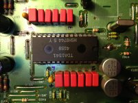
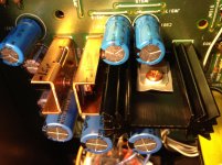
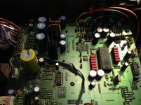
The resulting sound is already AMAZING and VERY improved compared to the original player, with all subective parameters moving from a very dull sound to a super dynamic and very spacialized Hi End sound. Cool!
BUT I have bumped into an issue trying to upgrade the clock. I have bought a chinese low jitter clock with the correct frequency of 16.9344 MHz. I have connected the board to a 5V direct from Voltage regulator (to the board plus input) and Ground Output to player ground. I have successfully measured the target frequency on the output connection. I know this is not a long term solution, I will build a dedicated Regulator for this card at 8VDC, but I wanted to conduct some tests.
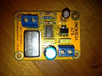
In order to implement this low jitter clock, I have removed the stock Quartz, and both caps (18pf) from the board. So basically I should have been just able to get the CD working just by connecting the new clock to one both holes, more or less. Well neither worked for me. I have tried to get some documentation but haven't been able to find a proper way to connect the clock board.
The problem comes from the fact that I have two ICs to clock, the CXD1088 (Digital filter) on which both sides of the stock Quartz are connected (pins 27 for XIN and 26 for XOUT) but WITHOUT a parallel resistor (as stated in most installation manuals), AND the CXD1125 (DSP) through a serial resistor of 1K (R524) (on pin 53 XTAI of the DSP).
I have tried every possible configuration for wiring the clock, bringing the clock signal to both XIN, XOUT, either sides of the serial resistor (R524), adding a parallel resistor of 470 Ohms... none solution seems to work. So I have tried to use my brain a little.
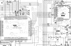
It comes to my mind that the CXD1125 is fed a clock signal from the XOUT pin of the CXD1088. This means that both XIN of CXD1088 and XTAI of CXD1125 are in opposing phase and there is no way that I can connect to both XIN and XTAI with the same clock, except if I put an inverter of some kind between XIN and XOUT of the CXD1088.
What puzzles me is that according to what I've read so far on the Internet, nobody seems to have had similar difficulties mounting this type of clock, but from what I understand by reading the Sony technical drawing, it is not as straightforward as I would have hoped on this particular Sony player.
Am I missing something here or is there really a trick to get both ICs clocked properly?
I would appreciate if someone could put me in the right direction to find a proper wiring.
Thanks guys, any comment would be much appreciated!!
Phil
Sorry to bother you guys with my lame thread. I am new around and would like some advice in order to try to adress my issue.
I have successfully conducted a very satisfying upgrade of my father's old CDP950 after having read Fikus (the Polish Mad Professor) blog for quite some time.
So far I've replaced all caps mainly with OsCon SEPC (I found them to have the best sound), PSU Caps with KA Nichicons, Diodes with old cascading Vishays for smooth response, changed the Voltage regulators for brand new ones, and bypassed all output resistor network to go directly to the RCA from the Opamp output (upgraded too) through Roderstein blue axial 47uF. Of course I have also switched the crapy ceramic around the DAC for 5 pairs of 220nF+1 pair of 470nF+1 pair of Tantal 2.2 uF (à la Fikus...mind the polarity of these two last ones, Plus sign must be farther from DAC on BOTH sides otherwise you'll hear something is wrong!!)...
Here's some pics of the (partialy) finished project


The resulting sound is already AMAZING and VERY improved compared to the original player, with all subective parameters moving from a very dull sound to a super dynamic and very spacialized Hi End sound. Cool!
BUT I have bumped into an issue trying to upgrade the clock. I have bought a chinese low jitter clock with the correct frequency of 16.9344 MHz. I have connected the board to a 5V direct from Voltage regulator (to the board plus input) and Ground Output to player ground. I have successfully measured the target frequency on the output connection. I know this is not a long term solution, I will build a dedicated Regulator for this card at 8VDC, but I wanted to conduct some tests.

In order to implement this low jitter clock, I have removed the stock Quartz, and both caps (18pf) from the board. So basically I should have been just able to get the CD working just by connecting the new clock to one both holes, more or less. Well neither worked for me. I have tried to get some documentation but haven't been able to find a proper way to connect the clock board.
The problem comes from the fact that I have two ICs to clock, the CXD1088 (Digital filter) on which both sides of the stock Quartz are connected (pins 27 for XIN and 26 for XOUT) but WITHOUT a parallel resistor (as stated in most installation manuals), AND the CXD1125 (DSP) through a serial resistor of 1K (R524) (on pin 53 XTAI of the DSP).
I have tried every possible configuration for wiring the clock, bringing the clock signal to both XIN, XOUT, either sides of the serial resistor (R524), adding a parallel resistor of 470 Ohms... none solution seems to work. So I have tried to use my brain a little.

It comes to my mind that the CXD1125 is fed a clock signal from the XOUT pin of the CXD1088. This means that both XIN of CXD1088 and XTAI of CXD1125 are in opposing phase and there is no way that I can connect to both XIN and XTAI with the same clock, except if I put an inverter of some kind between XIN and XOUT of the CXD1088.
What puzzles me is that according to what I've read so far on the Internet, nobody seems to have had similar difficulties mounting this type of clock, but from what I understand by reading the Sony technical drawing, it is not as straightforward as I would have hoped on this particular Sony player.
Am I missing something here or is there really a trick to get both ICs clocked properly?
I would appreciate if someone could put me in the right direction to find a proper wiring.
Thanks guys, any comment would be much appreciated!!
Phil
The new clock signal should go to the Digital Filter CXD1088 XIN pin 27. The XOUT signal feeds the DSP through the 1k resistor. There is an inverter internally between pin 27 and pin 26. Only the capacitors should be removed (as you did). Use a twisted wire and connect the GND close to XIN. I would not connect the GND at the power input terminal since might cause a ground loop.
Edit: Tantalum capacitors are very poor for audio. Also the upper two capacitos can be the same value. I recommend 470nF also for the MSB.
Edit: Tantalum capacitors are very poor for audio. Also the upper two capacitos can be the same value. I recommend 470nF also for the MSB.
Last edited:
Hey dear Oshifis !
THANKS a million for your advice!!!
This really help!!! Ok so I start to understand. The problem I had came from poor cabling only. I will try again with proper voltage and PSU for the clock board, will leave the ground as close as possible to XIN and will use twisted pair for clock/ground.
About the tantalum, I believe you, but Fikus states rather differently along with Arcam player implementation for this specific pair of coupling caps. I will give a try to your suggestion anyway!!
THANKS!!!!!!!!!!!!!!
Pin 28 seems the best for this purpose...will leave the ground as close as possible to XIN and will use twisted pair for clock/ground.
About the tantalum: just knock it with the grip of a screwdriver, and you'll hear the difference
Last edited:
As a mater of fact Oshifis, I have ordered a used TDA A version in China yesterday evening as I plan to do the NOS modification as well. Let's hope its not a fake one... I'll see how it works out to do just a straight switch first from my stock non A TDA (Fikus' favorite apparently). I will also change oscillator cap for a silver mica which is on its way. These mods won't bring much but just for the principle I'll give them a try.
I am mainly waiting for new opamps at the moment, but due to a postal employee stealing my parcels (6 since September), I have been waiting for the last 3 months to get these damned opamps (dual OP627AU, Dual AD797BR & OP2604AP). For the moment I am still using stock opamps 5532 which are rather not "up to date"
By the way, I have seen on the Sony tech doc that there is an EMPHASIS stage in parallel of the opamps. This stage is "switchable" but I don't have such an option neither on the remote control nor on the player itself. It's really a mystery.
I would like to remove as many as possible useless gimmicks. Any idea what I should remove here as some resistors in parallel are necessary for the opamps operation? I have spent the last 3 days looking for an explanation of such a stage but I couldn't even start to find an answer. This stage seems driven by several cascading transistors and seems to act on the opamps.
It looks really pathetic and I doubt that it's necessary to have 3 transistors there, not mentioning the power consumption that I'd rather give to the TDA...
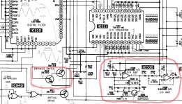
Any clue what this stage does?
I am mainly waiting for new opamps at the moment, but due to a postal employee stealing my parcels (6 since September), I have been waiting for the last 3 months to get these damned opamps (dual OP627AU, Dual AD797BR & OP2604AP). For the moment I am still using stock opamps 5532 which are rather not "up to date"
By the way, I have seen on the Sony tech doc that there is an EMPHASIS stage in parallel of the opamps. This stage is "switchable" but I don't have such an option neither on the remote control nor on the player itself. It's really a mystery.
I would like to remove as many as possible useless gimmicks. Any idea what I should remove here as some resistors in parallel are necessary for the opamps operation? I have spent the last 3 days looking for an explanation of such a stage but I couldn't even start to find an answer. This stage seems driven by several cascading transistors and seems to act on the opamps.
It looks really pathetic and I doubt that it's necessary to have 3 transistors there, not mentioning the power consumption that I'd rather give to the TDA...

Any clue what this stage does?
Last edited:
http://wiki.hydrogenaudio.org/index.php?title=Pre-emphasis#Pre-emphasis_on_audio_CD
Extra filter comprising R501, C508 and C509, is switched in by Q500. R521 and R502 maintain correct DC conditions. Q520 and Q522 switch on Q500. A bit complicated, but the switching has to be done quickly and smoothly, without injecting noise.
More a blind alley than a gimmick. Are you sure your favourite CD has no pre-emphasis applied? Power consumption isn't a concern. Snip the entire filter and switch if you don't want it.
Muting isn't a gimmick either. I like to insert my own noise between tracks. Music always sounds better in contrast to ten seconds of nails poured into a bucket.
Phil,
You should check this other thread:
http://www.diyaudio.com/forums/digital-source/193857-mod-cdp-sony-950-a.html
(done the search for you )
)
You should check this other thread:
http://www.diyaudio.com/forums/digital-source/193857-mod-cdp-sony-950-a.html
(done the search for you
You guys are incredible!! Many thanks for your replies...
PlasticIsGood, thanks for your help in identifying the useless components, I wasn't sure where to cut between the R500/C507 and the Emphasis stage (R501/R502 and below). Now everything is clearer.
Well actually to answer your question, with more than 6 thousands CD, I had no idea what this pre-emphasis thing was about, but it really reminds me of Dolby B/C NR era and my good old Sony Walkman that I had to carry around with 10 kg of tapes!! Wow almost stone age technology now!! This whole circuit goes down the tube indeed. For the mute stage, it is currently bypassed, but speaking with you makes me think that I may re-enact its usefulness when I move to NOS decoding, switching it on when on pause in order to avoid noise when not decoding (look for NOS hack you'll see what I mean).
Oshifis thanks for the link, I had already checked this thread, but did not look beyond the supercap discussion. Actually I figured the use of this part on my own Ha! But the thread seems longer than I thought, I'll have a look.
For your information, I have just decided to build a discrete JFet output stage as a first step toward lampization. (http://lampizator.eu/LAMPIZATOR/FETISHIZATOR/JFET_CDout.pdf). It seems quite cheap to build and sounds promising. I will order the parts this afternoon. Also I have spent last night deeply checking Caps parameters, and I believe that my choice of same value Nichicon KT series for pre Voltage Reg is wrong as ripple current values are lower than on stock caps (VX) for the + and - 5V. For the -15V I took a KT 50V rated instead of 35V stock, so this compensates and gives me same max ripple tolerance. Still I will try to put better suited caps there.
So I have ordered new high ripple caps with over-sized values for all 3 stages. NCC KY series for the -15V line, will be a 35V 1800uF and Rubycon YXG 25V 5600uF (slightly larger with 18mm diameter instead of 16mm original VX but it should fit right) for the +- 5V lines. It took me quite some time to pin point the best possible caps for sizing, highest possible ripple tolerance and if possible higher capacitance out of what ebay has to offer. Mouser would be too complicated right now for France unfortunately as they have almost everything in stock...
Ok guys a quick update here. Just applied the following modifications :
1/ I have changed the pair of Tentalum DAC decoupling caps (2.2uF 35V) for Wima (0,470 nF 63V 5%) as suggested by Oshifis.
2/ I have added a pull-down resistor (360k 1/4W) between live and ground on each channel to drain the output capacitor and reduce the output offset. This does not stop the player from Bumping loud when switched on/off though. It used to do it before I added the pull down resistors, and still does now. Compared with original stock diagram, I now only miss a 1k resistor in series after output cap and grounding with the 360k resistor (330k originally but I didn't have the value).
Maybe this in line 1k resistor is originally there to reduce this bump, but it's in line with the signal as well and I sure don't like that, as it acts as a voltage divider with the grounding resistor... But maybe it doesn't have any effect on the sounding apart from reducing the output level.
3/ I have added a pair of bypass caps (Wima 0,47uF 63V 5%) on each Voltage Regulator output capacitor (1000uF 16V) for each supply line (+5, -5 and -15V). By the way the stock capacitor is rated at 16V for a -15V line. Quite low specifications in my opinion. I will have to upgrade this.
BTW just a quick question if someone has the time to answer (this is an easy one). Is there a practical method (rounded calculation) to find the proper value of a bypass capacitor for such an application (HF filtering out of DC supply). I had read an excellent article few months ago analyzing all possible cases (on a simulation software) and concluding that apart from cascading between 5 and 10 decreasing value capacitors, HF filtering is close to null with one cap. Anyone to improve my hopes?
So now for the sounding. Well it has changed the rendering quite a bit actually. Much more than I would have thought.
-Dynamic and spacialization are unchanged, still huge compared to original version. There is nevertheless a great change in frequencies rendering.
-Lows are somehow increased in level and a bit less accurate (sort of very slightly greasy compared to before latest mods, but it may also come from my sound system specific bass roll-out as I have active monitors with separated sub).
-Highs are more rounded than with the tantalum capacitors. They used to be very finely defined, but slightly aggressive. This is totally gone now. I can crank up the volume without suffering from invading trebles. This change is the most noticeable.
-Mids are more pronounced and more defined. This is good as it helps spacialization and sensation of presence. The sound is very refined now, very hi-endy and smooth.
Conclusion
I don't think that the pull down resistor have had any effect on the frequencies rendering. Overall I think that Tantalums make a real difference and in my opinion are well suited for subtle music (Micro Plankton music as Fikus calls it). Well the poor guy loves Carla Bruni so I'll leave him with Tantalum for the moment and I'll stick with Wima which may be more suited for my music (Mega Plankton Music). Arf...
1/ I have changed the pair of Tentalum DAC decoupling caps (2.2uF 35V) for Wima (0,470 nF 63V 5%) as suggested by Oshifis.
2/ I have added a pull-down resistor (360k 1/4W) between live and ground on each channel to drain the output capacitor and reduce the output offset. This does not stop the player from Bumping loud when switched on/off though. It used to do it before I added the pull down resistors, and still does now. Compared with original stock diagram, I now only miss a 1k resistor in series after output cap and grounding with the 360k resistor (330k originally but I didn't have the value).
Maybe this in line 1k resistor is originally there to reduce this bump, but it's in line with the signal as well and I sure don't like that, as it acts as a voltage divider with the grounding resistor...
3/ I have added a pair of bypass caps (Wima 0,47uF 63V 5%) on each Voltage Regulator output capacitor (1000uF 16V) for each supply line (+5, -5 and -15V). By the way the stock capacitor is rated at 16V for a -15V line. Quite low specifications in my opinion. I will have to upgrade this.
BTW just a quick question if someone has the time to answer (this is an easy one). Is there a practical method (rounded calculation) to find the proper value of a bypass capacitor for such an application (HF filtering out of DC supply). I had read an excellent article few months ago analyzing all possible cases (on a simulation software) and concluding that apart from cascading between 5 and 10 decreasing value capacitors, HF filtering is close to null with one cap. Anyone to improve my hopes?
So now for the sounding. Well it has changed the rendering quite a bit actually. Much more than I would have thought.
-Dynamic and spacialization are unchanged, still huge compared to original version. There is nevertheless a great change in frequencies rendering.
-Lows are somehow increased in level and a bit less accurate (sort of very slightly greasy compared to before latest mods, but it may also come from my sound system specific bass roll-out as I have active monitors with separated sub).
-Highs are more rounded than with the tantalum capacitors. They used to be very finely defined, but slightly aggressive. This is totally gone now. I can crank up the volume without suffering from invading trebles. This change is the most noticeable.
-Mids are more pronounced and more defined. This is good as it helps spacialization and sensation of presence. The sound is very refined now, very hi-endy and smooth.
Conclusion
I don't think that the pull down resistor have had any effect on the frequencies rendering. Overall I think that Tantalums make a real difference and in my opinion are well suited for subtle music (Micro Plankton music as Fikus calls it). Well the poor guy loves Carla Bruni so I'll leave him with Tantalum for the moment and I'll stick with Wima which may be more suited for my music (Mega Plankton Music). Arf...
Ok I think it's time I update the community on the whereabouts of my quest to upgrade the CDP 950 Sony CD player.
Following our exchanges, I received several types of opamps.
I have rolled them under several types of music to determine which one was my favorite. It's been quite difficult as I've found the sound of the player to be lacking a little bit of punch lately.
Basicaly here's what I've done to the beast:
-Upgrade input caps of Regulators +5 and -5 lines with Rubycons YXG 25V 5600uF. They fit perfect but are quite bigger than stock ones. I had previously put some really dumb Audio caps there. Sorry I am a beginner and I learn from my mistakes. So after realizing the importance of ripple tolerance at this precise location, I switched to better adapted ones.
I still have a Nichicon KA 50V 1000uF for the -15V line. It's not perfect, but while I wait for Chinese to deliver their goods (KY NCC 1800uF 35V) I have to stick with this Nichicon, quite poor on Ripple tolerance (1040 mA)
-I've also upgraded Regulators Output caps with Philips 1500 uF 25V all 3 of them, it's more coherent after all to have all three equivalent. They are very close for +5 -5 lines, I couldn't get anything bigger or it wouldn't fit.
-I've upgraded the Opamps main caps from Rubycon MBZ 1500uF 10V to Nichicon Fine Gold (KW line) 2200uF 10V. This is only temporary as I'll be upgrading them again when I receive my biggest oscons (1500uF 16V SEPC Wow!). This will be the ultimate upgrade...
-I've switched the DAC oscillator capacitor (470 pf ceramic) for a silver mica same value
-I've done the same for both quartz capacitors as I've been forced to roll back the clock upgrade once more (see bellow)
-I've upgraded the decoupling caps for the DAC from my previous choice (220 nF * 5 then 470 nF * 2 all Wima MKS 5%) to 470 nF * 6 Wima MKS plus 1 * 2.2 uF Tantalum 35V Kemet. I tried Siemens Silver caps at 220 nF but found them really lacking attack, way too mellow and also they tend to short each others when packed closed together. Not good at all!! The 470 nF I chose to install require to be mounted one out of two underneath the PCB as they are too big to fit on top. That's fine as this CD player Sony is very forgiving with plenty of space bellow PCB.
I want to emphasis the enormous importance of these decoupling caps. Even if you end up with an ugly result, it is in my opinion of the first importance to choose big and quality caps to fit there. I would recommend no less than 330 nF (even if Philips spec says 100 nF). You can really hear the difference especially in trebles definition.
Also the last two caps (most significant bit them call them I believe), need to be even bigger, the last one the biggest of all. Between 1uF and 2.2 uF for this one seems a good value. Tantalums may be used for this one if you like a bit of dryness in your trebles. Mind polarity with these, plus sign is on the exterior of the DAC on both side. Contrary to previous posts, I confirm Lampizator theory and recommend Tantalums for the last cap, they sound quite excellent I have to say. Surprisingly they are less harsh than polyester films.
I can really say that sound has exploded when I changed these caps. At first I thought I had a problem as I could hear all defects of the recordings. But no problem, it was super high definition I was hearing!! Overall this is the most significant thing to do on a TDA 1541 DAC
-Upgrade of the DAC itself from TDA1541 to TDA1541A. I can't hear a difference at all...
-For the opamp it has been a very difficult choice, switching between three choices, AD797BR Dual Mono, OPA627AU Dual Mono and OPA2604AP. I would say that AD797 had the most details of all but slightly tend to be tiring. They require smoothness in speakers and/or amp or you'll get tired fast. 2604 are mellow and analogue but lack definition compared with latest opamps. Globally OPA 627 is an excellent compromise. It is well defined without being too rude in trebles.
-So now for the clock upgrade, I've managed to build a Voltage regulator to output some 9V, did what I was suggested, to connect the clock output at pin 27 and earth close to it. I even used a super nice silver coax to bring the clock there. It worked very well, and I was super mega happy for a while, when I realized I had a problem : The circuit is using 1.2 Amps at 17V !!
I almost set the player PSU on fire!! It was burning hot after one hour!! Got really scared!! After severe measures and measurments, I realized that my raw AC voltage was too high (17.5V), and could be 9 or even 8V AC in order for the L7809 to output proper 9V. Nevertheless I can say that my clock card drains no less than 520 mA @ 9V when in use. Does someone have any idea if this is a normal value? I guess it is. The problem comes from my voltage regulator overhead of 700 mA. I have to check with a lower voltage, and more importantly, buy a dedicated PSU!! Nevertheless compared with the stock quartz which runs on thin air, this clock card turns to be a real issue...
Any suggestions on proper values for power requirements would be appreciated!!
Thanks
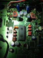
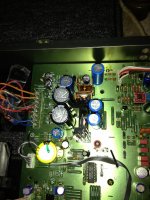


Hi Phil, you've picked a good player to modify, lots of room for improvement and not too many surface mount parts. I have a few comments about the project:
This is the result of removing the output muting transistors (Q401, Q402, Q501 and Q502). You can either live with the thumps and bumps, or install either a JFET or relay based muting circuit.
Sometimes this is the result of overly large decoupling capcitors on the active dividers. I'd focus less on large capacitors, more on trying some with better characteristics, like a Wima MKP2. I'd also try to keep to capacitors that fit in the PCB, long lead lengths aren't desirable here.
If you're buying from eBay, consider shopping at a proper electronics distributor. element14 has a better selection of brands, series, values and voltage ratings. Nippon Chemicon KZEs are a good option, they're the model up from the KY.
Just be sure to check they're not oscillating. Some of your proposed choices are very fast, they won't necessarily play nice where an NJM4560D would have.
That definitely doesn't sound right. It's either faulty, or a poor design, as you can't expect to be able to add this much load to a CDPs power supply. Besides that, it's not a great looking clock anyway.
I have added a pull-down resistor (360k 1/4W) between live and ground on each channel to drain the output capacitor and reduce the output offset. This does not stop the player from Bumping loud when switched on/off though.
This is the result of removing the output muting transistors (Q401, Q402, Q501 and Q502). You can either live with the thumps and bumps, or install either a JFET or relay based muting circuit.
Lows are somehow increased in level and a bit less accurate
Sometimes this is the result of overly large decoupling capcitors on the active dividers. I'd focus less on large capacitors, more on trying some with better characteristics, like a Wima MKP2. I'd also try to keep to capacitors that fit in the PCB, long lead lengths aren't desirable here.
It's not perfect, but while I wait for Chinese to deliver their goods (KY NCC 1800uF 35V)
If you're buying from eBay, consider shopping at a proper electronics distributor. element14 has a better selection of brands, series, values and voltage ratings. Nippon Chemicon KZEs are a good option, they're the model up from the KY.
For the opamp it has been a very difficult choice
Just be sure to check they're not oscillating. Some of your proposed choices are very fast, they won't necessarily play nice where an NJM4560D would have.
So now for the clock upgrade ... The circuit is using 1.2 Amps at 17V !!
That definitely doesn't sound right. It's either faulty, or a poor design, as you can't expect to be able to add this much load to a CDPs power supply. Besides that, it's not a great looking clock anyway.
A quick update on some very interesting upgrades I did the last couple of days.
I've been struggling pretty hard with the clock and a voltage regulator I built to supply it.
The clock board, quite a cheap one, was pictured earlier in the thread. It is based on a AMS1117-50 voltage regulator, and according to the specifications, I had to supply it with something between 9 and 12V DC ideally. Unfortunately, the CDP 950, as many TDA1541 based CD players, has only +5 -5 and -15V rails. I then started to build a regulator picking AC and outputing 9V, based on L7809CV.
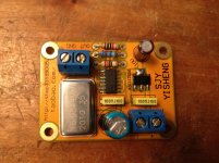
The clock Board
I tested my voltage regulator with a Variac and it seemed to power up fine, giving me a nice 9V output. But when I mounted it in the CD player, although, the clock was delivering its pace, I had a thermal runaway of the CD power supply. I suspected the clock board to have a defect of some sort. After many many tests I reinstalled the voltage regulator on AC +18 AND 0V (mid rail of AC supply of the player) and I had the same thermal issue. I measured Amps throughput to my voltage regulator and was above 1A of current! Still not working. But as 0V of the AC is also the ground of the DC, I suspected a bad input cabling shorting the L7809 to the ground. I tried to wire it with properly decoupled AC (+ AND - 9,5V). The same problem occurred again.
Damned!! It seemed that the line regulator I built, was delivering all it could to the ground as soon as it was connected to one, either directly or through the daughter board of the clock.
Tired of all this, I tried to wire the clock board directly to +5V (+4.9 in fact) just outside the CD line regulator caps. The clock board regulator AMS 117 instead of outputing 6.5V as expected just delivered 4.9V (same as its input). To my greatest surprise, it didn't affect the quartz operation at all. This one just worked perfectly fine at this low level of DC. The clock board consumed a mere 15mA. Now that what I call return to normality!!
I then proceeded to some listening tests and BOY what a surprise!! I thought improvements would be minor if even noticeable, but the sound of the player was transformed!! The music has now a MUCH improved depth!! The staging of the sound has immensely improved!! The result is quite insane I must say. I wouldn't have believed that previous clocking was lacking precision to this extent!! The result is absolutely noticeable and quite shocking, especially on string transients and voices rendering!! I would HIGHLY recommend this mod to all CDP users. Beware that many low jitter boards are on the market, some requiring AC and having SMD bridges on board, others such as mine, with just a SMD DC voltage regulator.
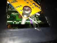
Mounting of the clock board under the main PCB with hex rod (isolated with washers) and a thumb screw to remove it... Simple and convenient
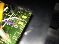
Piggy backing the +5V rail after output caps of the main regulators. Bypass Tantalums are added to purify the DC line as much as possible.
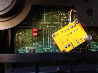
Overall view of the setup from below the CD player.
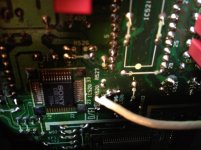
Clock link to PCB (pin27 of the digital filter) with silver plated & Teflon coax
I have also checked my opamps for oscillation as suggested in previous post. They tend to be a bit hot to the touch after few minutes of output, but nothing to be alarmed of so far. The sound is really clear as crystal without being harsh. I will test them with an oscilloscope once I get one next month. I will have a look at the AD797 documentation and see how they differ from the original 5532 topology for the feedback loop. I may need to modify some resistors or caps around the opamps, as I understand it.
I have tried to find proper polypropylene caps to put a final touch to the decoupling of the DAC. Unfortunately, possibilities are very limited due to the size of these caps. I would have to go for 0.15 or if even possible size-wise, to 0.22uf caps. I'll be ordering some soon and will let you know the results.
For the moment, I've settled with:
- 0.47 MKS Wima 63V 5% for the 5 first caps (mounted upside down for one out of two)
- Wima 2.2uf MKS (I think) 63V at 2.5% for the 6th
- Kemet tantalum 2.2uf at 35V for the last one (see picture)
This is the absolute best setup I've found so far especially with the AD797 opamps. Sound is super clear and spacious with so much depth you can just dive into it!!
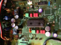
Decoupling configuration of the DAC, the best I've reached so far...
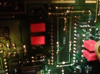
Below the PCB there's more room for caps which don't fit under the sun...
So now one last for the road... What about this voltage regulator I've built... It seems to work fine as long as it is not grounded. But as soon as I ground it, it outputs as much as it can. If the chassis is the ground, it overheats the PSU of the appliance. If house ground is present it make the main house fuse goes offline!! I've check every possibility and cannot find any problem to the circuit.
I have 4 diodes bridge, then 2 caps, one 2200 uF 25V, one 0.1 uF both in parallel between VCC input and Ground, then the L7809 (properly grounded on the middle pin, no shorts between pins or radiator), then 2 other caps parallel between VCC output and the ground (one 1000 uF 16V, one 0.1 uF), and lastly a diode with a limiting resistor of 300 Ohms, both in series, and mounted also parallel just as the caps. As long as no ground is present I get a nice 9V but as soon as I ground this, it just outputs like mad!!
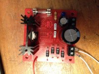
The voltage regulator, with two AC in and linked to ground. In this config it either makes the main fuse goes off (if earth is ground), or if chassis is ground, makes the appliance PSU burn...
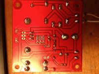
The PCB from below
I don't understand what is going one. Maybe one cap is not bypassing anymore, but I've checked all spec for all components and none seems out of specs. PCB also tests OK.
I suspect the diode and resistor to possibly be the weak point but I've been told it could not be the case... I mean this circuit is like ABC of electronics and I can't even make it run properly.. I'm so depressed, please help me!!
I've been struggling pretty hard with the clock and a voltage regulator I built to supply it.
The clock board, quite a cheap one, was pictured earlier in the thread. It is based on a AMS1117-50 voltage regulator, and according to the specifications, I had to supply it with something between 9 and 12V DC ideally. Unfortunately, the CDP 950, as many TDA1541 based CD players, has only +5 -5 and -15V rails. I then started to build a regulator picking AC and outputing 9V, based on L7809CV.

The clock Board
I tested my voltage regulator with a Variac and it seemed to power up fine, giving me a nice 9V output. But when I mounted it in the CD player, although, the clock was delivering its pace, I had a thermal runaway of the CD power supply. I suspected the clock board to have a defect of some sort. After many many tests I reinstalled the voltage regulator on AC +18 AND 0V (mid rail of AC supply of the player) and I had the same thermal issue. I measured Amps throughput to my voltage regulator and was above 1A of current! Still not working. But as 0V of the AC is also the ground of the DC, I suspected a bad input cabling shorting the L7809 to the ground. I tried to wire it with properly decoupled AC (+ AND - 9,5V). The same problem occurred again.
Damned!! It seemed that the line regulator I built, was delivering all it could to the ground as soon as it was connected to one, either directly or through the daughter board of the clock.
Tired of all this, I tried to wire the clock board directly to +5V (+4.9 in fact) just outside the CD line regulator caps. The clock board regulator AMS 117 instead of outputing 6.5V as expected just delivered 4.9V (same as its input). To my greatest surprise, it didn't affect the quartz operation at all. This one just worked perfectly fine at this low level of DC. The clock board consumed a mere 15mA. Now that what I call return to normality!!
I then proceeded to some listening tests and BOY what a surprise!! I thought improvements would be minor if even noticeable, but the sound of the player was transformed!! The music has now a MUCH improved depth!! The staging of the sound has immensely improved!! The result is quite insane I must say. I wouldn't have believed that previous clocking was lacking precision to this extent!! The result is absolutely noticeable and quite shocking, especially on string transients and voices rendering!! I would HIGHLY recommend this mod to all CDP users. Beware that many low jitter boards are on the market, some requiring AC and having SMD bridges on board, others such as mine, with just a SMD DC voltage regulator.

Mounting of the clock board under the main PCB with hex rod (isolated with washers) and a thumb screw to remove it... Simple and convenient

Piggy backing the +5V rail after output caps of the main regulators. Bypass Tantalums are added to purify the DC line as much as possible.

Overall view of the setup from below the CD player.

Clock link to PCB (pin27 of the digital filter) with silver plated & Teflon coax
I have also checked my opamps for oscillation as suggested in previous post. They tend to be a bit hot to the touch after few minutes of output, but nothing to be alarmed of so far. The sound is really clear as crystal without being harsh. I will test them with an oscilloscope once I get one next month. I will have a look at the AD797 documentation and see how they differ from the original 5532 topology for the feedback loop. I may need to modify some resistors or caps around the opamps, as I understand it.
I have tried to find proper polypropylene caps to put a final touch to the decoupling of the DAC. Unfortunately, possibilities are very limited due to the size of these caps. I would have to go for 0.15 or if even possible size-wise, to 0.22uf caps. I'll be ordering some soon and will let you know the results.
For the moment, I've settled with:
- 0.47 MKS Wima 63V 5% for the 5 first caps (mounted upside down for one out of two)
- Wima 2.2uf MKS (I think) 63V at 2.5% for the 6th
- Kemet tantalum 2.2uf at 35V for the last one (see picture)
This is the absolute best setup I've found so far especially with the AD797 opamps. Sound is super clear and spacious with so much depth you can just dive into it!!

Decoupling configuration of the DAC, the best I've reached so far...

Below the PCB there's more room for caps which don't fit under the sun...
So now one last for the road... What about this voltage regulator I've built... It seems to work fine as long as it is not grounded. But as soon as I ground it, it outputs as much as it can. If the chassis is the ground, it overheats the PSU of the appliance. If house ground is present it make the main house fuse goes offline!! I've check every possibility and cannot find any problem to the circuit.
I have 4 diodes bridge, then 2 caps, one 2200 uF 25V, one 0.1 uF both in parallel between VCC input and Ground, then the L7809 (properly grounded on the middle pin, no shorts between pins or radiator), then 2 other caps parallel between VCC output and the ground (one 1000 uF 16V, one 0.1 uF), and lastly a diode with a limiting resistor of 300 Ohms, both in series, and mounted also parallel just as the caps. As long as no ground is present I get a nice 9V but as soon as I ground this, it just outputs like mad!!

The voltage regulator, with two AC in and linked to ground. In this config it either makes the main fuse goes off (if earth is ground), or if chassis is ground, makes the appliance PSU burn...

The PCB from below
I don't understand what is going one. Maybe one cap is not bypassing anymore, but I've checked all spec for all components and none seems out of specs. PCB also tests OK.
I suspect the diode and resistor to possibly be the weak point but I've been told it could not be the case... I mean this circuit is like ABC of electronics and I can't even make it run properly.. I'm so depressed, please help me!!

The AC input of the regulator must be floating. Center tapped causes a short through the on board diodes.
Yes Oshifis this is precisely what happens!! I've identified the bridge of diodes as the source of feedback to the ground.
Sorry I feel really stupid here. So just to make sure I fully understand your quote, this means that both AC- and AC+ of the regulator board must be floating. This means that this type of regulator cannot be used on a 0-xV type of rail of a PSU. Hummmm quite annoying... Thanks for the help!
The problem comes from the fact that I have two ICs to clock, the CXD1088 (Digital filter) on which both sides of the stock Quartz are connected (pins 27 for XIN and 26 for XOUT) but WITHOUT a parallel resistor (as stated in most installation manuals), AND the CXD1125 (DSP) through a serial resistor of 1K (R524) (on pin 53 XTAI of the DSP).
It comes to my mind that the CXD1125 is fed a clock signal from the XOUT pin of the CXD1088. This means that both XIN of CXD1088 and XTAI of CXD1125 are in opposing phase and there is no way that I can connect to both XIN and XTAI with the same clock, except if I put an inverter of some kind between XIN and XOUT of the CXD1088.
Phil
Hi,
At the risk of being a bit off-topic, I have a Denon DCD1420 which uses Sony CXD1125 DSP and SM518 filter implemented in as similar way as the CXD1125 and CXD1088 mentioned by Phil in the first post. i.e the crystal “in” is on the SM5813’s XTI pin (5) on the filter chip and then taken from the XTO pin (6) to the CXD1125 XTAI (pin 53).
The BB PCM54 DACs in the player I have were fried when I acquired it and so I want to convert it to just a transport. The CXD1125 puts out SPDIF from pin 27 and the digital out works just fine through my DAC, so as far as I can tell, with no DACs downstream of it, the only thing the SM5813 now does is to supply a clock signal to the CXD1125’s XTAI pin.
My question is, can I remove the existing crystal from the SM5813 and insert a new XO type clock module on the CXD1125? There is even provision for a crystal and capacitors on the PCB right beside the CXD1125.
I note that Phil mentioned that he thinks the XTO of the filter and the XTAI of the CXD1125 are in opposing phase. Am I right in assuming that if I swapped the crystal/XO to the CXD1125 and rendered the filter inoperable, the relative phase would not be an issue?
I would be grateful for any help.
Joe
- Status
- This old topic is closed. If you want to reopen this topic, contact a moderator using the "Report Post" button.
- Home
- Source & Line
- Digital Source
- Sony CDP950 Tweaking Problem with XO clock upgrade