got an old working philips cd 584 and did some modifications. After adding decoupling caps to the TDA1541, changing the output caps, fiddling with the opamp it all played fine, but when I replaced 33 uf and 47 uf caps with equivalent oscons the player resets itself at certain tracks and re-reads the disk like it was just inserted, otherwise it plays fine, but when it reaches a loud part of a track, well it resets.
I've checked the voltages on the new caps, reheated all the solder contacts (except smds), swapped power supply rectifiers for shottkys (1N4002->11DQ10)... nothing helped. I am thinking the player somehow runs out of juice, but the parts I've fiddled with seem fine. I am wondering what could cause the player to reset? Any help is much appreciated.
I've checked the voltages on the new caps, reheated all the solder contacts (except smds), swapped power supply rectifiers for shottkys (1N4002->11DQ10)... nothing helped. I am thinking the player somehow runs out of juice, but the parts I've fiddled with seem fine. I am wondering what could cause the player to reset? Any help is much appreciated.
Why loud parts I wonder?
My first inclination would be to reverse the last modification. Have you thrown the old caps away? In which positions did you put the oscons?
In some situations, an ESR much lower than in the original design might cause instability. How the control of the mech could be related to loud bits isn't obvious to me. Audio section power supply ringing infecting the digital ground maybe.
Do you have an oscilloscope and a circuit diagram?
Why loud parts I wonder?
I also wonder why. My reasoning is that the digital section should work regardless of the signal or not work at all. Since the player resets on tracks like hero's return form pink floyd which has a loud beginning I thought maybe there is not enough juice reaching the dac.
hero's return:
Pink Floyd - The Hero's Return (Parts I & II) (45 rpm single) - YouTube
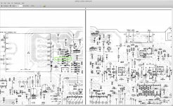
People owning a Rega planet had similar problems with the player restarting. Replacing the rectifier diodes solved the problem there. This player has two rectifier bridges (schematic attached)
I've reversed part of the caps reaching the transport. In the power section I've beefed things up - larger caps shouldn't hurt here? Also added caps around the dac.My first inclination would be to reverse the last modification. Have you thrown the old caps away? In which positions did you put the oscons?
The old caps are safely stored
") I'll revert first the caps around the dac and the filter chip.
I'll revert first the caps around the dac and the filter chip.I should mention when swapping the opamp I've placed it the wrong way in and burned the 15V voltage regulator (yellow sqare) on the power section. The player worked fine after replacing the voltage regulator with a new one. Then the oscons arrived and with them new problems.
There was a 33 uf oscon which had huge voltage drops when playing and I've replaced it with a 47 oscon. Thought this was it, the voltage was stable, but it made no difference.
Unfortunately a multimeter is all I have. Also my knowledge about electrical devices is very limited. That's why I chose a simple, cheap cd-player with a tda1541 dac to learn on it.In some situations, an ESR much lower than in the original design might cause instability. How the control of the mech could be related to loud bits isn't obvious to me. Audio section power supply ringing infecting the digital ground maybe.
Do you have an oscilloscope and a circuit diagram?
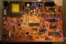
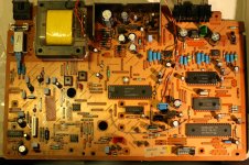
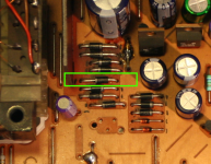
Attached is a picture of the board:
- yellow square right 100 uf output caps replaced with fresh 100 uf nichicons.
- yellow left is the 15V voltage regulator smoked (and replaced) when I accidentally put the opamp wrong way in
- violet squares are oscons. I've exchanged 33 uf 16V for 33 uf 20V oscons and 47 uf 25V for 47 uf 16V oscons. (tda1541 from schematics needs 15V supply voltage).
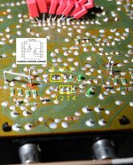
This is where the reset error occured, added more oscons, measured all voltages. Where I could not measure I've replaced the white underlined caps with the originals and the 33 uf caps in the power section with the 100 uf bipolars from the audio section (which work). Replaced one 33 oscon with 47, because it was discharging rapidly while playing / under load.
- green marks the rectifier bridges and 3 additional diodes of the same kind (1N4002) exchanged for schottky's 11DQ10
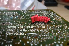
On the bottom side of the board:
- added larger decoupling caps to the dac
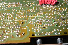
- messed up the pcb on the audio output caps while trying to attach a too thick wire to the pcb to connect some large mundorf film caps, reverted to new nichicons
- found a crack on the pcb - where I've put some solder to fix the contact
Attachments
-
 IMG_7123-small.jpg315.7 KB · Views: 273
 -
philips-cd582-cd584.1-16.pdf747 KB · Views: 73
-
philips-cd582-cd584.17-18.pdf887.8 KB · Views: 67
-
philips-cd582-cd584.19-24.pdf914.9 KB · Views: 82
-
 decoupling-caps.jpg243.2 KB · Views: 268
 -
 pcb-damage.jpg298.5 KB · Views: 275
 -
 pcb-crack.jpg296 KB · Views: 254
Did you replace any of the 33uF/47uF caps in the area under the CD mechanism ??
If so, they must be the same type and value i.e. not oscons.
Andy
no, the three 33 uf caps in that area were restored with the original ones and that did not make a difference
Just zooming in on the third picture and the soldering looks a bit suspect tbh. Two components, one at left and one at the right look really dry.
Thanks for all the replies! Added some solder there and replaced the 47 uf 16 V oscon near the dac with the original 47 uf 25 V nichicon. Now the player plays the track that causes the reset for 13 s... which is an improvement
The voltage measured is 14,89 V so I don't see why the 47 uf oscon would make a difference, but somehow it did (maybe the ESR issue mentioned earlier?).Now I'm replacing the 47 uf oscons in the power supply area... fingers crossed
16 seconds of music
Now all the oscons are reverted back with the original caps, checked the schematics if I made a mistake and mixed up some caps, but all looks fine (was not so hard since there were only three 47 uf caps replaced, the rest was 33 uf).
Rechecked all the contacts, added some solder here and there and cleaned with contact spray (teslanol). The player makes it a whole 16 s into track 5 and then resets.
took out the opamp in the output stage.. no change
well the board looks much less colorful without the oscons
Attachments
Last edited:
Chin up! I'd be happy with a player that refused to play Pink Floyd.
Your headphone amp's the wrong way round. 4560D, top right.
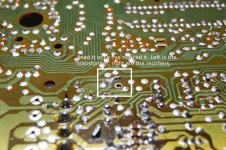
I would remove that blob of solder over the crack in the track, and use a wire link. The way you've done it, it could be that the solder has only taken to the bare edge of the crack, and a little flexing could break the joint. Clean back a section of track to bare copper before you solder...a fibreglass pencil is good but fine abrasive paper will do. The board tends to flex due to the weight of the transformer. They can crack from the back of the audio socket to the front of the heatsink too. The tracks are flimsy, as you've found.
Carefully remove all the solder splash (from using a solder sucker?). I agree with Mooly that some joints look dry. Is your iron hot enough?
Are you sure that track played before? The single-board CDM4 machines can be a bit choosy about CDRs, I find.
Your headphone amp's the wrong way round. 4560D, top right.
I would remove that blob of solder over the crack in the track, and use a wire link. The way you've done it, it could be that the solder has only taken to the bare edge of the crack, and a little flexing could break the joint. Clean back a section of track to bare copper before you solder...a fibreglass pencil is good but fine abrasive paper will do. The board tends to flex due to the weight of the transformer. They can crack from the back of the audio socket to the front of the heatsink too. The tracks are flimsy, as you've found.
Carefully remove all the solder splash (from using a solder sucker?). I agree with Mooly that some joints look dry. Is your iron hot enough?
Are you sure that track played before? The single-board CDM4 machines can be a bit choosy about CDRs, I find.
Chin up! I'd be happy with a player that refused to play Pink Floyd.
Your headphone amp's the wrong way round. 4560D, top right.
I would remove that blob of solder over the crack in the track, and use a wire link. The way you've done it, it could be that the solder has only taken to the bare edge of the crack, and a little flexing could break the joint. Clean back a section of track to bare copper before you solder...a fibreglass pencil is good but fine abrasive paper will do. The board tends to flex due to the weight of the transformer. They can crack from the back of the audio socket to the front of the heatsink too. The tracks are flimsy, as you've found.
Carefully remove all the solder splash (from using a solder sucker?). I agree with Mooly that some joints look dry. Is your iron hot enough?
Are you sure that track played before? The single-board CDM4 machines can be a bit choosy about CDRs, I find.
Ok, no more pink floyd
I've played mike oldfield now, and it played the whole cd flawlessly. Then I've placed back the cover and it reset at track 4, which is kind of loud. If I let it cool down a few minutes and remove the cover it plays the normally again. I guess it's a heat issue.
Thanks for the advice, you are absolutely right about the headphone opamp. Things are starting to make sense now. Some time ago I tried replacing the headphone opamp with NJM5532 or opa2134 and the 15 V regulator (yellow square) started burning. Then I've replaced the burned 78L15 ACP 826 with L78L15ACZ TO-92 for 100mA.
-> and it gets quite hot. I'll try replacing it with a bigger 2A 15V regulator with a heatsink (have to order one). It would make sense that when it overheats the new voltage regulator has heat protection and switches off for a short period... and the cd player resets.
Hm, my soldering temperature is 350-400 C. New solder looks more smoth on the surface and the old solder is whiter or pale, sometimes I've added some new solder to old contacts, then it's a mix. I also get some dark stuff mixed in, probably carbon I rub the solder iron against to get rid of excess solder. Is this what you meant by dry joints?
Thanks for all the help!
forgot to attach the bottom side headphone section showing the opamp should be in the other way round
PlasticIsGood:
yes, the CDM4 does not like to play CDRs, a workaround is to burn them at slower speed and then it reads them. This pink floyd cd is an original and it was read without problems
PlasticIsGood:
yes, the CDM4 does not like to play CDRs, a workaround is to burn them at slower speed and then it reads them. This pink floyd cd is an original and it was read without problems
Attachments
I find lead-free solder hard to work with, so I always use the old lead/tin stuff. It seems to mix OK with whatever's already there. A dry joint is one where the solder has failed to "wet" the metal. This can be because of contamination, or too low a temperature, but also maybe because it's too hot and the flux is burning before it does its work.
Where the solder meets the wire, there should be a fillet where it's flowed up the wire, not a depression where it looks like it's been repelled by the wire surface. Perhaps a cooler iron, for a little longer, in your case. Fresh flux should always be present at the join whilst soldering, so don't use the iron to transport the solder to the joint.
Soldering instructions seem never to say what temperature is best. I've found around 275C is OK for lead/tin, allowing quick work to avoid overheating the components. Other solders need to be hotter, but it's hard to tell by how much.
I think the 4560 is used because it copes well with a relatively low resistance at it's output. When looking for an alternative, check for minimum load resistance, or some indication of distortion v output current. Better, make yourself a headphone amp.
Some regulators can ring or oscillate if a too-low ESR cap is used close to the output. They need the damping provided by the cap's resistance. Your oscons are probably best placed around the decoder and filter chips, but you really need an oscilloscope to check if the change is for better or worse. Transferring noise from power to ground, especially without absorbing any of its energy, can be counter-productive.
I got a nice Philips dual-trace, 60MHz scope off ebay for not much money. Much more fun than a multimeter.
Chin up! I'd be happy with a player that refused to play Pink Floyd.
I once had a cd player that would only play 2 Eric Clapton cds and nothing else.
Obviously, some players have taste !!
.
I find lead-free solder hard to work with, so I always use the old lead/tin stuff. It seems to mix OK with whatever's already there. A dry joint is one where the solder has failed to "wet" the metal. This can be because of contamination, or too low a temperature, but also maybe because it's too hot and the flux is burning before it does its work.
Where the solder meets the wire, there should be a fillet where it's flowed up the wire, not a depression where it looks like it's been repelled by the wire surface. Perhaps a cooler iron, for a little longer, in your case. Fresh flux should always be present at the join whilst soldering, so don't use the iron to transport the solder to the joint.
Soldering instructions seem never to say what temperature is best. I've found around 275C is OK for lead/tin, allowing quick work to avoid overheating the components. Other solders need to be hotter, but it's hard to tell by how much.
I think the 4560 is used because it copes well with a relatively low resistance at it's output. When looking for an alternative, check for minimum load resistance, or some indication of distortion v output current. Better, make yourself a headphone amp.
Some regulators can ring or oscillate if a too-low ESR cap is used close to the output. They need the damping provided by the cap's resistance. Your oscons are probably best placed around the decoder and filter chips, but you really need an oscilloscope to check if the change is for better or worse. Transferring noise from power to ground, especially without absorbing any of its energy, can be counter-productive.
I got a nice Philips dual-trace, 60MHz scope off ebay for not much money. Much more fun than a multimeter.
Tried today with ~300 C for soldering and it is much better. I was using higher temperature, because I saw somewhere that for desoldering it was better and then I continued using it for soldering as well... maybe not the best idea
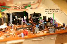
I replaced the 78L15 TO-92 100mA regulator with a 78S15 TO-220 2A and a resistor (yellow-violet-gold-gold) which had the gold multiplier stripe broken and measured 16 Ohm istead of 4,7 Ohm.
Not to make the trip to the electronics shop just for a regulator I also came back with some capacitors. Basically the power section has all new caps now. And the filter chips have the oscons back.
I'd say the sound is a tad cleaner, but it still won't play all my cd's... it resets (reproducibly) at the same spots of different tracks usually when some drums start to kick in
I'll give it another try tomorrow and stick tonight (again) to one cd that plays without problems
Attachments
The content on the CD can't have any possible connection to it cutting out. That sounds like a mechanical/disc issue.
I totally agree, but I'd like to cancel out a few possibilities and understand better so please correct me where I am wrong. My reasoning was that in the digital section the receiver or filter either work or not, since there is zero's and ones to process i.e. are content independable. The cd's sampling rate is 44.1 kHz meaning there is always the same amount of info to parse. Therefore content should not matter at all.
What about the tda1541a? It converts the signal to current, so if there is a faulty decoupling or supplying capacitor and does not recharge fast enough the dac runs out of current. Could that cause the player to reset or would the signal just grow weaker - more silent? But I am not experiencing any fluctuations in volume, the player plays normally until it resets at certain tracks.
On the other hand, if I am looking for a mechanical issue. The cd's are fine, tested on 4 original cd's that all played fine before and some CDRs. Interestingly, Mike Oldfields songs of distant earth is brand new and plays to the end without any problems if the lid is open. However, if the lid is closed it causes the player to reset at the beginning of track 4, which has a loud beginning (some spaceship rockets sound). Seems like something is overheating. That's why I've started looking at the power section and voltage regulators, but there's not much left to look at there
Could it be the cd mechanism got damaged during the few dozen times I've assembled and disassembled the cd player or maybe some bent cable? I can't help but wonder why a closed lid would make a difference? And the reset is reproducible to the second.
Getting my hands on an oscilloscope would show me what happens to the signal on reset and would definitely be more fun than using a multimeter
. Have to save up some money first The DAC has no bearing on the servo operation as such. Nothing is fed back from the DAC to the front end.
All these issues started after you began changing parts... is that correct ?
If supply rail had a problem then that could cause any manner of problems but its not likely to be related to signal content. The difference in current drawn by the DAC wouldn't modulate the supplies in practice.
Again a scope is THE tool to use to really see whats going on.
If its overheating and/or the fault is reproducible to the second then try pausing the player for a few minutes before the problem part of the track and see if it still cuts out at the same point.
thanks for the explanation, makes things clearer nowThe DAC has no bearing on the servo operation as such. Nothing is fed back from the DAC to the front end.
this means the problem lies in the cd mechanism or servo part or the power section
yes it played without any problemsAll these issues started after you began changing parts... is that correct ?
If supply rail had a problem then that could cause any manner of problems but its not likely to be related to signal content. The difference in current drawn by the DAC wouldn't modulate the supplies in practice.
Again a scope is THE tool to use to really see whats going on.
If its overheating and/or the fault is reproducible to the second then try pausing the player for a few minutes before the problem part of the track and see if it still cuts out at the same point.
maybe the transformer is overheating / failing?
after playing to the end of songs of distant earth with the cover off and repeating the cd it resets itself on track 4
I've let the cd player coold down for 10 min and the same error (note that the voltage regulators all cooled down in this time, but the transformer was still hot). After one hour of being switched off it doesn't reset at track 4 anymore.
Tried the other cd which resets exactly 16s on track 5. If I pause at 10s into track 5 for about 10 min and press play it again resets at 16s. (the transformer is still cool).
If I want to measure voltages on capacitors supplying the cd mechanism the mechanism has to be removed to gain access to those parts. I am a bit reluctant to power on the cd player without all cables attached, but it would be vastly faster if I did not have to assemble the whole player each time I test something. How do you guys measure voltages across the board?
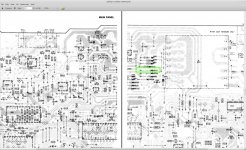
started looking at the schematics a bit more and found a discrepancy. There's a diode rectifier pointing the other way around as in the schematic. Unfortunately I haven't made a picture of the unmodified board, but I've marked the directions before exchanging them (can't 100% exclude I've made an error
though).
update: the schematics on the next page shows the diode in the other direction like it is on the board now
I can't burn parts if I switch the orientation of the diode, right? There will be just half the sinus converted or?
The reset error started before the diodes were replaced! That's why I've replaced them
Attachments
Last edited:
If you get the diode the wrong way round it can cause damage because it would rectify the "wrong" half of the cycle and give a negative instead of positive voltage for example. If it were in a bridge then it would overheat. The PCB diagrams are too faint to really see whats going on but you should be able to work it out from the circuit diagram.
That glass ??? looking diode in the picture looks frazzled.
Too many issues seem to have arisen with all this. With the greatest respect I think you have to realise that the work you have done is probably the cause of all the problems.
That glass ??? looking diode in the picture looks frazzled.
Too many issues seem to have arisen with all this. With the greatest respect
I think you have to realise that the work you have done is probably the cause of all the problems.- Status
- This old topic is closed. If you want to reopen this topic, contact a moderator using the "Report Post" button.
- Home
- Source & Line
- Digital Source
- help philips cd 584 resets