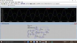
The TL082 is used as a conventional differential voltage converter. You can see the voltage levels for 0db output in this old simulation of the CDP790 stage. Vout and Vsum overlay each other at 1kHz.
Choice of the TL082 is probably down to commercial (cost) reasons as much as anything.
Definitely do not try and increased the shared rail voltages as that would likely cause problems/damage to the servo and pickup circuitry. Purists will argue the shared rail will have some HF noise it from the digital sections... is it a problem... only a blind AB test of a different setup would say for sure.
I tried different opamps in the 790 (on a small SIL to DIL board) and found the TLE2072 which is latest improved version of the original TL0xx series would not reach 0db output without clipping. The 5 volt rails are right at the lower limit of being able to achieve 0db output and opamp choice is critical here.
Attachments
Thanks Mooly!
Thinking that the rail-to-rail OPA211 won't be a problem for headroom at +/-5V but not sure about the ADA4627-1 (which is my favorite sounding op amp).
Do you have any thoughts on the impact of the supply capacitor upgrades I noted in post 135? My thinking was that the additional filtering would help to clean up the two supplies and perhaps keep some of the digital noise out of the analog stage (not that I can hear it). What I didn't mention is that I also added 0.47μF and 1000μF directly across the rails at the output, underneath the ICs. I know that oscillation is a potential issue, but don't know enough to say whether it would be here.
Another possibility is increasing headroom in the headphone section by switching to unregulated +/-10V from the main filter capacitors instead of the regulated ~+/-4.7V it is currently receiving. As mentioned, I've already added two 1000μF 16V FR capacitors there. Note that, even though I use K702s, I tend to keep the volume well below 12:00, perhaps closer to 9:00 depending on the loudness of the CD, so I'm not sure how much voltage swing is really necessary.
On a side note... either the forum software or my browser (Firefox) is adding double spaces between paragraphs and I can't seem to stop it. Not my formatting choice!
In general I never like to be drawn on cap questions and whether they really make a difference... if it sounds better to you then that is all that matters in the end. High frequency oscillation issues usually respond better and more consistently to careful application of a series resistor and cap (like a 1 ohm carbon and a 0.1uF) which is reproducible and consistent. Electrolytics have deteriorating performance at higher frequencies due to their internal self inductance.
As always, using a good scope will show if there really is any noise on the rails, and the real test is always to live with any modifications for an extended period and then see whether you feel the improvement is lasting.
Double spacing... we've had that happen before and it was browser related as I recall.
Here we go:
double and triple space between paragraphs after Preview Post
I'm using Edge Dev, the 'work in progress version' of Edge that gets updated a couple of times a week and this one is based on Chromium open source. Have to say I'm finding it excellent all round.
double and triple space between paragraphs after Preview Post
I'm using Edge Dev, the 'work in progress version' of Edge that gets updated a couple of times a week and this one is based on Chromium open source. Have to say I'm finding it excellent all round.
In general I never like to be drawn on cap questions and whether they really make a difference... if it sounds better to you then that is all that matters in the end. High frequency oscillation issues usually respond better and more consistently to careful application of a series resistor and cap (like a 1 ohm carbon and a 0.1uF) which is reproducible and consistent. Electrolytics have deteriorating performance at higher frequencies due to their internal self inductance.
As always, using a good scope will show if there really is any noise on the rails, and the real test is always to live with any modifications for an extended period and then see whether you feel the improvement is lasting.
A friend gave me his old Tektronix 454... which should work for checking for noise on the line, no? How would you suggest I go about it? Haven't really used it much. Was thinking of looking at the rails with no CD is playing, then whilst playing a disc, and seeing if there's any difference.
As mentioned previously, I can't really say if I heard a difference with the upgraded supply capacitors. Adding them might have firmed up the bass a bit, but I couldn't say for sure. On the other hand, replacing the 47μF coupling caps at the output with a much larger electrolytic and a pair of film caps made a very clearly audible difference... for the better.
Also tried burning some test CDs to see if I could hear or possible see or measure any clipping at the output only to find that my new burner or the media I have on hand won't play; guessing the reflectivity is very low.
Note: I switched from the enhanced editor to the standard version... no more double spaces.
I seem to remember the KSS240 would only play CDR's (I think it would play those), but certainly not CD-RW.
To look for noise on the rails you need to first make sure the scope is connected correctly to the relevant power supply ground in the player. Touching the probe tip to this point should then give a straight trace with no noise although in practice you will probably pick up something small due to mains grounding of the scope and any loop effects of the probe leads. It should be very very small though.
From there you can look for any AC content on the rail using AC coupling for the scope Y amplifier and using a high sensitivity setting.
Separating the supplies with a new PSU board with the right voltages for opamps will make this device a lot better. No crossfeed, no HF and no headroom issues with low cost. An hours work including the drilling. I won't start about the clock but you can have mine for shipping costs. It is a 45.xx MHz Tent on a separate PCB with PSU. Best would be to give it a separate transformer too to avoid GND loops.
Last edited:
Separating the supplies with a new PSU board with the right voltages for opamps will make this device a lot better. No crossfeed, no HF and no headroom issues with low cost. An hours work including the drilling. I won't start about the clock but you can have mine for shipping costs. It is a 45.xx MHz Tent on a separate PCB with PSU. Best would be to give it a separate transformer too to avoid GND loops.
Thanks, jean-paul.
It's sounding pretty good to me now with the current modifications, a little better than my modified TC Impact Twin. What sort of audible improvement should one expect from adding separate supplies with higher rails? Or would it be more of a theoretical advantage?
Haven't played with clocks very much except in terms of listening for differences when I change master/slave clocking on my various recording interfaces. Noticed some subtle things in terms of small details and stereo imaging.
It is another way of looking at designs. Shared rails between digital and analog electronics are technically undesirable and such can easily be measured. +/- 5V is a known design error by Sony which you can eliminate. It is too restricting for best results. Both drawbacks are added in this device. For me it is a no brainer to solve design errors first and then try different caps. Trying out opamps when the supply voltage is at the absolute minimum might set you on the wrong foot. Loosing time on marginal things when the basis is not OK is futile. Trying to "get away" with least effort techniques will not work out, the manufacturer already did so.
A good clock is essential for best results. I modded an extreme amount of CD players in the past of all brands and types. In fact the bad sound quality of CD players when they were introduced was the reason I started with this hobby. After a while one knows a bit which things have impact on the final results. As cost cutting and thus bad or mediocre PSU's were standard I designed my own symmetrical PSU boards (and clock PCB's) to eliminate such issues. Well designed PSU's are a very large part of the final outcome.
Of course all this is old news as optical media and CD players meanwhile have become the dinosaurs of audio.
Anyway, send me a PM for the clock. I have another one for the thread starter of a different brand/type.
Last edited:
Anyway, send me a PM for the clock. I have another one for the thread starter of a different brand/type.
Thanks JP, I appreciate that but its an old thread now and I don't use the player at all these days I'm afraid
")
For a bit of background, I bought my first CD player in 1986, a Sony CDP-65, which sounded a tad harsh to my ears. After that I got a CDP-C435 which seemed a bit smoother, but still wasn't that great, IMO. Eventually, both Sonys developed mechanical problems. Next was an old NAD 5000 given to me by a friend which had some disc reading issues and didn't sound a good as my modified Echo Gina24 interface. All those players went to the recycling depot a few years ago and I was without a dedicated CD player until just recently.
I made no significant modifications to those old CD players. However, I have built a variety of electronic projects over the years including a version of the A/DA flanger, as well as made a number of modifications to various pieces of musical gear like my bass amp, effects pedals, recording interfaces, etc... much of it focusing on op amp and capacitor upgrades.
A couple of months ago I bought a used Luxman DZ-112 with double PCM1701 converters. It required a new belt so I fixed that up. I was curious to hear if its Burr-Brown resistor ladder DAC would be audibly superior to my various interfaces with more modern delta-sigma DACs. However, I found it somewhat underwhelming to listen to, at least through the headphone output with my K702s; the sound seems somewhat muffled and "lo-fi". It also has some disc reading issues and I suspect it requires laser focus/tracking adjustment.
Then I spotted the CDP-X111ES for $20 and bought it the same day. Initially, it sounded thin and inferior to the output of my modded TC Impact Twin. So, I thought I'd start with the low hanging fruit, that being upgrading the output coupling capacitors and op amps, along with adding a few new Panasonic FRs on the rails. With the current tweaks, it sounds a little better than my modded TCIT, which is to say surprisingly good, and significantly better than the DZ-112. Note that I've been doing my listening comparisons through the various devices' headphone outputs, not the main outs.
If I were to design a CD player from the ground up, I agree with using separate supplies and higher power rails for the analog stages. However, with the X111ES, I was simply trying to get the biggest improvement without having to re-engineer the design, which is why I tried the caps/op amps approach first, as I had parts on hand and it was quick and easy to do.
That said, I'm willing to consider making more substantial modifications if a good case can be made for it. That's why I asked if there would be an audible improvement from adding separate power rails with higher voltages (and/or upgrading the clock). If so, what sort of differences should one expect to hear?
Last edited:
Its hard to say what any audible differences would be, or if those differences were strong enough that you could pick them out in blind testing. That said, there could be a valid case for running opamps at higher voltage. It should be easy enough to alter the board to do this as a test.
Its hard to say what any audible differences would be, or if those differences were strong enough that you could pick them out in blind testing. That said, there could be a valid case for running opamps at higher voltage. It should be easy enough to alter the board to do this as a test.
According to Douglas Self, running the OPAMPS at higher voltage provides more dynamic range, which I suppose means a greater voltage swing.
I note that a lot of his designs use +-18v rails.
I run most of mine at +-12v and I can't say I noticed any difference boosting the voltage, so I suspect that beyond a certain voltage there's a point of diminishing returns.
Likewise, I've not noticed any difference in noise (to the limits of what I can measure with my home setup) or THD.
The changes would be measurable and you will hear it. The PSU would be a lot cleaner than it is now and the opamps would be running at more sound voltages giving them some breath. That is the case. As I have a day off I just went through my stock and I even found some PSU boards (some original Sony from more well thought out devices by them). I also haven't noticed differences above +/- 12V except in power amplifiers with opamps as drivers where one definitely needs the maximum voltage swing.
If it would not make a difference Sony themselves wouldn't design the more expensive models with these features (I would think).
It makes little sense to describe the effects (high risk of audio blah blah) but I am sure one will appreciate it.
Same goes for replacing mute transistors (which are non linear) for relays, better low noise regulators, separate PSU for the clock circuit etc. All of this has been discussed here numerous times.
If it would not make a difference Sony themselves wouldn't design the more expensive models with these features (I would think)
.It makes little sense to describe the effects (high risk of audio blah blah) but I am sure one will appreciate it.
Same goes for replacing mute transistors (which are non linear) for relays, better low noise regulators, separate PSU for the clock circuit etc. All of this has been discussed here numerous times.
Last edited:
The most plausible way to run higher voltage to the op amps would seem to be by drawing +-10V (unregulated) from the output of the rectifier bridge, just before the input of IC202. That would require cutting the +-5V traces going from the regulators to the analog stage. Is there another way, a better way, for test purposes? Also, would it be detrimental to feed unregulated power to the output op amps (noise, ripple, etc...)? I have a variety of electrolytic capacitors around for extra supply bypassing, but no regulators.Its hard to say what any audible differences would be, or if those differences were strong enough that you could pick them out in blind testing. That said, there could be a valid case for running opamps at higher voltage. It should be easy enough to alter the board to do this as a test.
FWIW, I'm not saying that there's no difference if adding a separate supply with higher rails. Rather, I'm just trying to get an idea how much of a difference there might be and whether or not it would be worth doing. I haven't made a mod like this before.
2.5V RMS output equals roughly 3.5V peak-to-peak, which could be pushing it for 5V rails. Not sure if this player is that high, or closer to 2V nominal.
On a side note, I briefly compared the main outputs of the DZ-112 and CDP-X111ES into my Rotel RC-850 through my K702s. They definitely sound different. The DZ-112 seems to have a somewhat warmer sound with more emphasis on the bass and lower midrange, whilst the X111ES is more detailed, but perhaps more "clinical".
Attachments
I know that when I tried different opamps on my player that the -/+5v rail was a limitation that could actually be seen on a scope at full output.
Cutting traces is actually a super neat way of achieving the switch because it is so easy to reinstate back to original form if needed.
A little extra decoupling would be worthwhile if you try this, perhaps something like series 39 ohm resistors and 100uF would be a good starting point.
Cutting traces is actually a super neat way of achieving the switch because it is so easy to reinstate back to original form if needed.
A little extra decoupling would be worthwhile if you try this, perhaps something like series 39 ohm resistors and 100uF would be a good starting point.
Please no resistors when a separate PSU is used. Sometimes there are jumpers in the supply rails that can be removed. Better use an existing solder pad than cutting traces.
Hi jean-paul.
Saw your post about the PSU and clock boards, which seems to have disappeared. Thank you for the offer. Please do not think I am ignoring your advice. I am just starting out with CD player modifications, so I am moving slowly at first, trying to get a better idea of what modifications are best. I may be interested in more serious modifications, but need a little time to think them through.
There's a star party this weekend, so I will likely be out late with my telescope for the next couple of days/nights.
Last edited:
Guessing that it is best to continue discussing CDP-791/X111ES modifications here rather than starting a new thread?
What about using the existing +/-10V unregulated rails to feed two LD0 9V regulators for the op amps? I'd like to avoid adding another transformer if possible, in part because it would complicate the power switching, requiring further hacking. Looking at the circuit, I'm not even sure how I'd switch the power to an additional transformer.
A separately regulated and well decoupled analog supply from a common transformer may not be as good as using a separate transformer, but still should be significantly better than running analog and digital circuits off of the same source. Also thinking that +/-9V ought to be enough to guarantee sufficient headroom, no?
On a side note, I tried switching the positions of the ADA4627-1s and OPA211s, moving the OPA211s to the differential stage and the ADA4627-1s to the output. IMO, it sounds much better this way, unexpectedly so... punchier in the lows, with more detail, and less "clinical". IMO, the ADA4627-1 is one of the best sounding op amps (though I am a bit concerned it may not have enough headroom with the existing 5V rails).
On another side note, I brought out my old PC with a Lite-On LTR-52327S CD burner and the CDs it burns are playable in the X111ES, unlike when the same batch of CDs are burned with the newer ASUS DRW-24F1ST in my new PC.
I used to find that burning at the highest speeds gave the best results (looking at the eye pattern on playback) which is the opposite of what you generally read.
The -/+10 volts are unregulated and so you really need to view these on a scope to see exactly what the peaks and troughs are. 1 volt headroom isn't much to play with, on the other hand they could be considerably higher than 10v.
Increasing the -/+5v to even -/+7v would still be a worthwhile gain imo and remove the possibility of clipping at maximum level from opamps that are running right at their limits.
- Home
- Source & Line
- Digital Source
- Sony CDP790 and KSS240 Restoration Project