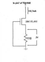
I invite everybody to try this simple JFET current source-if you have not already made it-instead of the 1K resistor on the TDA1543 voltage reference at the pin 7.
In my set up the output resistors are 1K too. This application produce a better soundstage , better dinamics and more precision in details in the entire audio band .
... at least in my set up🙂

Cheers
In my set up the output resistors are 1K too. This application produce a better soundstage , better dinamics and more precision in details in the entire audio band .
... at least in my set up🙂
Cheers
Attachments
Dr.H said:What happens to the circuit values when 8 TDA1543 are used?
It need a different resistor value.
**********
With TDA1543 at 5volt power supply I choose the above 2.7mA current that reflects at the output - with I/V resistor=1K- 3.3volts.
It can be done also with a current like ... say 2mA.
So 2mA *8=16mA.
The resistor in the circuit above is tipically:0.3/I
For 8 TDA1543 in parallel R= 0.3/16m =0.3/0.016=18,7ohm
**********
If you want a slightly higher current decrease that resistor value.
🙂
Hello Stefano,
I think I'll try your solution (among the half thousand I'd like to try it is simple enough and can be switched on/off for camparison purpose)
Correct me if I'm wrong, giving a quick look at the datasheet the current that exits from AOR and AOL is the difference between Ibias (that is the current from pin 7) and Idac, so Ibias must be > Idac(max), that is 2.65 mA.
Thus the Rload must be chosen to have Vcc/2 on AOR and AOL in order to have the maximum voltage swing..->>Rload = (Vcc/2)/Ibias
Is this consideration correct? Are there other things to take in account?
Cheers
Andrea
Andypairo said:Hello Stefano,
I think I'll try your solution (among the half thousand I'd like to try it is simple enough and can be switched on/off for camparison purpose)
Correct me if I'm wrong, giving a quick look at the datasheet the current that exits from AOR and AOL is the difference between Ibias (that is the current from pin 7) and Idac, so Ibias must be > Idac(max), that is 2.65 mA.
Thus the Rload must be chosen to have Vcc/2 on AOR and AOL in order to have the maximum voltage swing..->>Rload = (Vcc/2)/Ibias
Is this consideration correct? Are there other things to take in account?
Cheers
Andrea
Hallo Andrea,
Your reasoning looks to me pretty correct.
Probably , according to the datasheet , it is better to calculate with more precision the I/V resistor value for a low harmonic distorsion.I am however a bit confused where the Ifs (full scale 2.65mA )comes from , since the I bias is adjustable and the current trough the I/V resistor is in my case > of the Ibias
😕
Hi stefanobilliani,
As I am a certain FAN of the great LINEARITY , I should gently inform you that this current source will not be as linear as you might expect if the voltage across the fet is varying! I.e. if there is any voltage signal on it's output. I would rather prefer a more complicated current source or a BJT one with Voltage accross the Iset resistor at least 5 Volts.
Keep this in mind if you are about to use passive /resistor/ I-V convertor.
On my oppinion, the current source should sink 1/2 of the max output current of the DAC, so it outputs +/- 1/2 Ioutmax, instead of 0-(+Ioutmax) -> I.e. this is current shifting.
Regards
machinow said:Hi stefanobilliani,
As I am a certain FAN of the great LINEARITY , I should gently inform you that this current source will not be as linear as you might expect if the voltage across the fet is varying! I.e. if there is any voltage signal on it's output. I would rather prefer a more complicated current source or a BJT one with Voltage accross the Iset resistor at least 5 Volts.
machinow, thanks for your reply, well:
the Jfet is used as a current source for the pin 7 or voltage refernce for the TDA1543 and just to be precise it is not used in the output I/V stage.
From the TDA1543 datasheet Vref variations are from a min of 2.10V to a max of 2.30V.Constant current sources offer a fixed constant current at large variations of V applied. Jfets normally have a negative gate voltage and so they conveniently forms a self-biased current source as shown.The datasheet of the 2SK170 shows clearly the linearity zone at 2volts and 2.5mA of operation, so here what is the problem?
machinow said:
On my oppinion, the current source should sink 1/2 of the max output current of the DAC, so it outputs +/- 1/2 Ioutmax, instead of 0-(+Ioutmax) -> I.e. this is current shifting.
Regards
I made experiments using the ohm's law from the original passive circuit that is 1k for the pin 7 and both 1k for the I/V stage outputs.
With that values the voltage at the output is 3volts (before the capacitor ofcourse) and the vref pin 7 is nearly the same 2.2 volts or so.As you can see I altered the current for the pin 7 from a 2.2mA to a 2.7mA that shifts the output to 3.3V.Is that too much?
Regards🙂

stefanobilliani said:
I made experiments using the ohm's law from the original passive circuit that is 1k for the pin 7 and both 1k for the I/V stage outputs.
With that values the voltage at the output is 3volts (before the capacitor ofcourse) and the vref pin 7 is nearly the same 2.2 volts or so.As you can see I altered the current for the pin 7 from a 2.2mA to a 2.7mA that shifts the output to 3.3V.Is that too much?
Regards🙂
I'd say it depends on which voltage you are operating it from.
If you use 5V it is probably too high, if you use 7V you can go even higher.
The output current is equal to Ibias (=2*Iref)- IDac , which is sunk by a controlled current sink.
Therefore the "zero" signal current for IDac should be 2.65 mA /2 (if we take the maximum value).
In your case with 2.2 mA Ibias = 4.4 mA and AOR should source about 4.4 - 1.325 = 3.075 mA * 1k = 3.075V
With 2.7 mA you probably saturated the bias current source at 5 mA (its rated maximum), so in this case we should have a theoretical 5- 1.325 = 3.675 V... not corrisponding to the actual value.
Can anyone explain why?
Cheers
Andrea
rbroer said:Have a look at Vref when music is playing 😎
Hallo rbroer ,
I do it just now... it is stable at 2.120V with-or-without music.
😎
Andypairo said:
I'd say it depends on which voltage you are operating it from.
If you use 5V it is probably too high, if you use 7V you can go even higher.
The output current is equal to Ibias (=2*Iref)- IDac , which is sunk by a controlled current sink.
Therefore the "zero" signal current for IDac should be 2.65 mA /2 (if we take the maximum value).
In your case with 2.2 mA Ibias = 4.4 mA and AOR should source about 4.4 - 1.325 = 3.075 mA * 1k = 3.075V
With 2.7 mA you probably saturated the bias current source at 5 mA (its rated maximum), so in this case we should have a theoretical 5- 1.325 = 3.675 V... not corrisponding to the actual value.
Can anyone explain why?
Cheers
Andrea
Ok Andrea ,
I apologie for non-precise numbers regardin my "effective working values".
I must say first that the current source runs in real life at 2.3mA couse the tipical negative voltage of the jfet is not so tipical and it is 0.254volt and not 0.3v.The vref as above mentioned is 2.120 stable with or without music. I measure 3.212 v at one channel output resistor that is something like 985 ohm.
That's all.
Updating
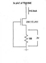
After correct measure of the crucial parameters I update the first post schematic:
If -Your- jfet looks like this for a 2.3mA current the resistor is 130ohm. Otherwise is better measure the jfet vgs for precise current setting.
2.7mA as shown in the first post is just too much
🙂
After correct measure of the crucial parameters I update the first post schematic:
If -Your- jfet looks like this for a 2.3mA current the resistor is 130ohm. Otherwise is better measure the jfet vgs for precise current setting.
2.7mA as shown in the first post is just too much
🙂
Attachments
Andypairo said:Stefano,
which Vcc do you use?
5V or higher?
Cheers
Andrea
Aaah! Here we go ! I use now 6.15Volts
😱
😀
Well, with 6.15Vcc the "ideal" output voltage (halfway between the minimum and maximum value given by the datasheet) is (6.15-1.2-1.8)/2 +1.8 = 3,375 V, so I think you have a quite perfect idle voltage.
Cheers
Andrea
PS Do you still use your balanced version?
Cheers
Andrea
PS Do you still use your balanced version?
Do you still use your balanced version?
I like very much balanced operation but I paused it for a while couse I was searching for a different PS to power it and a more detailed and precise sound .Now the ASR is battery powered and I use fets for the TDA 6.15volts. Finally , the current source .

Spectacular result...now I'm ready and back for the balanced version.
🙂
I'd be very happy if you could post a complete schematic of your setup... mine is halfway between Doede's and the convertus, but I think I'll include the ASR soon, so it will be ready for balanced operation!
BTW should the ASR (and its clock) have its own PS? (I guess so..)
Cheers
Andrea
BTW should the ASR (and its clock) have its own PS? (I guess so..)
Cheers
Andrea
OK Andrea . I'll see what can I do to post a decent schematic of my setup.😎
Regarding the ASR the answer is yes.Currently I power it with batteries.One for the clock and one for the sinchronizer.
The difference between PS and battery here is noticeable.
Regarding the ASR the answer is yes.Currently I power it with batteries.One for the clock and one for the sinchronizer.
The difference between PS and battery here is noticeable.
- Status
- Not open for further replies.
- Home
- Source & Line
- Digital Source
- Active Current Source for TDA1543