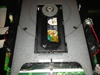
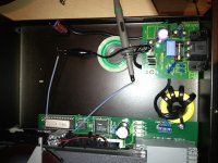
I have replaced the dead laser (there were no movements and motor didn't spin the CD) with CDM12.4/05 as should be and my Primare is alive")
Everything is fine expect that 10% of CDs are skipping on one or two tracks, mostly in the first seconds. Some of them are quite scratchy and I could understand the issue, though others have little and barely noticeable marks, so that makes me feel puzzled.
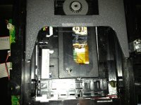
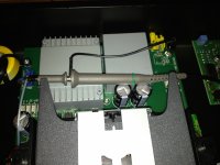
The whole mechanism has been replaced very carefully and pot on the laser's head has been adjusted in similar position to the previous one. Is there something wrong with the laser itself or some other adjustments could be made?
Everything is fine expect that 10% of CDs are skipping on one or two tracks, mostly in the first seconds. Some of them are quite scratchy and I could understand the issue, though others have little and barely noticeable marks, so that makes me feel puzzled.
The whole mechanism has been replaced very carefully and pot on the laser's head has been adjusted in similar position to the previous one. Is there something wrong with the laser itself or some other adjustments could be made?
Altering the pot "to match the other" is (could be ) a fatal mistake. The pot is calibrated such that the laser power is correct for that pickup.
All is not lost however, unless turned up significantly too high the laser won't self destruct. You need to play a known good red book standard disc (any commercial CD in other words but NOT a CDR or RW) and adjust the pot to give around 1.5 volts pk to pk RF measured on the outout of the RF amplifier. That point will be available on the main PCB, you don't have to try and measure on the pickup itself.
From a realistic and practical point of view, the quality of a lot of the so called new CDM12.4's on the market is terrible. They are not original Philips parts and can be anything from poor copies to reclaimed parts. It may just be a duff laser assembly.
) a fatal mistake. The pot is calibrated such that the laser power is correct for that pickup.All is not lost however, unless turned up significantly too high the laser won't self destruct. You need to play a known good red book standard disc (any commercial CD in other words but NOT a CDR or RW) and adjust the pot to give around 1.5 volts pk to pk RF measured on the outout of the RF amplifier. That point will be available on the main PCB, you don't have to try and measure on the pickup itself.
From a realistic and practical point of view, the quality of a lot of the so called new CDM12.4's on the market is terrible. They are not original Philips parts and can be anything from poor copies to reclaimed parts. It may just be a duff laser assembly.
Altering the pot "to match the other" is (could be
thanks mate!
I'm pretty sure that the adjustments I made didn't make the things worse as it skipped same tracks before the adjustment.
adjust the pot to give around 1.5 volts pk to pk RF measured on the outout of the RF amplifier. That point will be available on the main PCB
that could be a bit difficult for me. How can I trace that rf amp?
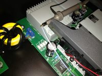
The RF amp is on the CDM12.4 but you get to the RF on the other end of the ribbon cable.
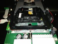
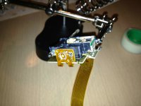
Its pin 9 or 10 on the TDA1302 IC on the pickup. You would have to see where that goes on the main PCB.
The RF is usually dead easy to pick up when you start measuring. Often there is a test point or some such. Obviously without the knowing the player I can't say exactly but you'll find it for sure following the output pins on the TDA1302.
Skipping on the CDM12 is often mechanical such as dried grease etc. That was the big problem with the original Philips stock 20 years ago.
according to TDA1302 pinout, RF amplifier is 10th pin, however it's almost impossible to get to the ribbon cable and take the measurements. What I did is turned on the player without a CD and measured the pot (there are even soldered marks for that, so I supposed this is how it should be adjusted). I set the voltage to 0.92 vdc as on my other working VAM1205 laser on T+A
To be honest it skips almost the same tracks as previously when it was accidentally set by me in 1.05 position. However few tracks now are readable. That is a good point! I have also tried other adjustment positions in the range of 15-85% of the pot scale. The lowest voltage is about 0.55 and highest is 1.07 where laser is unable to read the CD.
So I guess it's the problem of the laser, probably it's not that good as original Philips lasers.
Attachments
The measurement of approximately 1.5 volts pk to pk is as viewed on a scope. There's no other way to do it. If its difficult to access then you can solder a wire tag to connect the probe to.
It does sound like a suspect pickup. Even 6 years or so back I returned two CDM12.4's back to the supplier (I won't name them but they are one of the biggest suppliers to the repair trade). I was sent a boxed "Japanese" made CDM12.4 mech that was absolutely unbelievable in quality. The RF was amongst the cleanest I have seen. The other pickups looked and even smelled used and dirty.
No easy answer I'm afraid.
Yes, pin 15 but connect to the ground on the main PCB. There will be different "grounds" such as digital or signal. All are essentially the same but if you connect the scope to the wrong one the RF will look a bit noisier than it really is. To initially find the RF though you can just use the chassis ground for convenience.
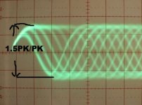
It should look like this,
NDP 4 Quality Assurance
Thats a typical good quality signal. I would assume the scope is on 0.05V/Div and using a divide by 10 probe. So around 1.5 volts pk/pk.
It should look like this,
NDP 4 Quality Assurance
Thats a typical good quality signal. I would assume the scope is on 0.05V/Div and using a divide by 10 probe. So around 1.5 volts pk/pk.
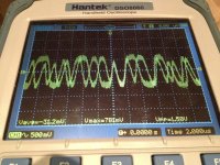
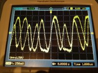
here are few pics I made. It seems to me that I got the wrong ground as the signal is quite noisy, though it's attached to the chasis bolt. Anyway I adjusted the pot to get roughly 1.50vdc on the scope (Vpp value changes very quickly from 1.42 to 1.60 according to the scope's build in functions). The probe is connected to soldered pure silver 0.3mm wire for hi-end audio measurement
It's working fine now, at least doesn't skip tracks that were fine before
thanks for new experience and your advices, Mooly
One last question to clarify, if I get a bit noisy signal, perhaps I should set the pk 2 pk value a bit higher, say some 1.55 average?
P.S. the coupling was set to AC on the scope, is that fine?
Attachments
It doesn't look like it should Maybe its some artifacts of the digital scope and the complex waveform... can't say for sure.
It should be absolutely as like in the picture in the link in the post above.
Going to 1.55 v won't affect things unduly. The reason the signal seems to jump suddenly when the pot is turned is because the point at which laser action begins is sudden. As current increase through a laser diode it functions more like a side emitting LED until suddenly the lasing action occurs and then small changes in current show as dramatic changes in laser output. Thats why the laser current is tightly controlled in a closed loop system.
AC couplings fine. DC coupling just shows the signal sat on top of whatever DC bias is present.
Maybe its some artifacts of the digital scope and the complex waveform... can't say for sure. It should be absolutely as like in the picture in the link in the post above.
Going to 1.55 v won't affect things unduly. The reason the signal seems to jump suddenly when the pot is turned is because the point at which laser action begins is sudden. As current increase through a laser diode it functions more like a side emitting LED until suddenly the lasing action occurs and then small changes in current show as dramatic changes in laser output. Thats why the laser current is tightly controlled in a closed loop system.
AC couplings fine. DC coupling just shows the signal sat on top of whatever DC bias is present.
the wire till the probe is about 10cm. Transformers do not affect on the signal noise I assume as I've tried move the probe.
When I stop the CD I get a huge noise still - it's about 0.3v pk 2 pk, when I disconnect the mains, no noise appear on the scope, so I guess I need to play with the grounds. I'll try to solder another wire to 15th pin of the chip to check if that helps...
When I stop the CD I get a huge noise still - it's about 0.3v pk 2 pk, when I disconnect the mains, no noise appear on the scope, so I guess I need to play with the grounds. I'll try to solder another wire to 15th pin of the chip to check if that helps...
morning!
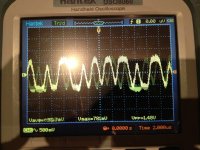
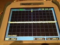
so I soldered another wire and took the ground directly from the ribbon cable. This helped to lower the oscillations to 140mv pk 2 pk. The signal looks like that now.
Unfortunately, still some discs skip. Also I found out that once you adjust the voltage to ~150mv it could be 130-135mv on the other CD that is more scratched and about 160-1.65mv on almost new CD. Is that ok?
Attachments
It doesn't look right and I don't know why. It should look like this whether it be a £10 portable or a £10,000 player. There's no variation in what you see. It should be rock steady and unvarying.
Maybe the (digital) scope isn't resolving this... I don't know. It wouldn't play if the RF really looked like that.
It's normal to see some variation between discs because the reflectivity varies a little. Take a disc that seems an "average" although most are fairly consistent.
Maybe the (digital) scope isn't resolving this... I don't know. It wouldn't play if the RF really looked like that.
It's normal to see some variation between discs because the reflectivity varies a little. Take a disc that seems an "average" although most are fairly consistent.
Attachments
- Status
- This old topic is closed. If you want to reopen this topic, contact a moderator using the "Report Post" button.
- Home
- Source & Line
- Digital Source
- Primare laser change