Not in the CEN IV circuit.
The added bonus is that Zin of the IV now equals Zout of the opamp.
And since the open loop gain is >120dB, and open loop output impedance is <1k,
you can argue that the OPA1641 Zout in follower mode would be <0.001 ohm.
And no, I don't have measurements to prove.
But yes, we have a PCB and will try it out some time.
")
Patrick
The added bonus is that Zin of the IV now equals Zout of the opamp.
And since the open loop gain is >120dB, and open loop output impedance is <1k,
you can argue that the OPA1641 Zout in follower mode would be <0.001 ohm.
And no, I don't have measurements to prove.
But yes, we have a PCB and will try it out some time.
Patrick
below is a simmed comparison of the PCM1704 datasheet I/V on the left and the noise gain compensated ADA4637 with higher feedback C
jcx , to compensate the ada4637 that is compensate to gain >5 , I think that is need a 10 ohms resistence in serie with c1 ,or at high frequencies c1 will bring gain below 5 . Or am I missing something ?
R3 and C3 forms a snubber, and snubbers are very good in limiting (dV/dt).
I think adding r3 and c3 is a good idea and can be use with compensated to unity gain opamp.
Last edited:
smms
these documents are informative.
Thanks for the literature, Shinja. It comes very handy.
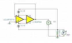
I use the OPA1641 in one of my phono amps in the second stage. I biased it into class A and added a buffer. That way it worked so well that a discrete design was not better.
Really interesting, did you ever tried OPA827?
Yes, i prefer the OPA1641 but the OPA827 is very good too. I also preferred the ADA4627 slightly over the OPA827. That is not based on measurements but only on listening.
The differences for me where slight though except for one woman in my listening panel that found the differences pronounced and send me a long list of surveys.
It is a bit like wine tasting. The longer and more eager you listen the more differences you find. I would say in a blind ABX test the differences will be swapped. I value topology higher in importance then swapping opamps anyway. In I/U converters we must be really sure that the opamps do not slew and snubbering and integrating is the right way to go i think. I just got back a digital preamp i friend of mine builds since many years and it sounded much better then before. I asked him what he did and he answered that he uses a bigger integrating cap now. The sound was much more analog like. Richer and more fluid without any loss of detail. I think he uses the LME49990.
Yes, i prefer the OPA1641 but the OPA827 is very good too. I also preferred the ADA4627 slightly over the OPA827. That is not based on measurements but only on listening.
Thanks Joachim
In my listening tests I preferred the OPA828, richer and fuller sounding in tested configuration (an old Sony CDP-797).
The OPA1641 was really interesting but as already posted seemed a bit current challenged (power consumption figures are suspect in this regard, IMHO) , you tested it with the buffer and class A biasing?
jcx , to compensate the ada4637 that is compensate to gain >5 , I think that is need a 10 ohms resistence in series with c1 ,or at high frequencies c1 will bring gain below 5 . Or am I missing something ?
R3 and C3 forms a snubber, and snubbers are very good in limiting (dV/dt).
I think adding r3 and c3 is a good idea and can be use with compensated to unity gain opamp.
nominally I chose the "noise gain" as ~ C3/C1+1
I included R3, trimmed its value to show less ringing on the Vin - the exact value depends on what the op amp Zout looks like at the gain intercept frequency - which may not be accurately modeled
but you could look at R3 as being in the noise gain ratio with the op amp Zout
you really shouldn't try this noise gain campensation with such a fast chip (or the much faster AD8067) without a 100+ MHz 'scope to see if there are problems, adjust the values from the sim
Last edited:
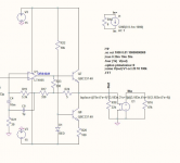
Here is the second stage of my phono RIAA where you can see the principle. Ignore the name of the Opamp and the inbuilt EQ in the feedback loop.
Wow, thanks!
Not in the CEN IV circuit.
The added bonus is that Zin of the IV now equals Zout of the opamp.
And since the open loop gain is >120dB, and open loop output impedance is <1k,
you can argue that the OPA1641 Zout in follower mode would be <0.001 ohm.
And no, I don't have measurements to prove.
But yes, we have a PCB and will try it out some time.
Patrick
Don't get too excited about this circuit. It's actually worse than a "normal" IV converter using opamps, either in terms of noise or distortion. I believe what you would want if you do this is the lowest possible output impedance for the opamp which is why I added the buffer.
Attachments
c3/c1+1 is right .nominally I chose the "noise gain" as ~ C3/C1+1
I included R3, trimmed its value to show less ringing on the Vin - the exact value depends on what the op amp Zout looks like at the gain intercept frequency - which may not be accurately modeled
but if you add R3 in series with C3, you should also add a resistor in series with C1 in this case a value 5 times higher than R3.
I think that there is no problem using lead-lag compensation in faster opamps.
Adding R3 as I said before is a good idea.
Thanks for sharing
Last edited:
- Status
- This old topic is closed. If you want to reopen this topic, contact a moderator using the "Report Post" button.
- Home
- Source & Line
- Digital Source
- I/V using opamps