Is that the complete mech including pickup or just the pickup alone you replaced ? The fault is essentially unchanged from what you say though, it plays for so long before audio cuts out.
I really don't have anything new to suggest to you. Its a tough fault and it needs a scope to try and find a way in to what is going amiss.
I really don't have anything new to suggest to you. Its a tough fault and it needs a scope to try and find a way in to what is going amiss.
I replaced the pickup mechanism (motor and spindle) section. After getting no joy from that and noticing that a gentle tap on the rear of the mechanism gets it playing I checked and reseated the mounting rubbers.
Careful visual inspection of the pcb should reveal cold solder joint and/or hot spot.
Boky
Hi Boky
Thanks for the suggestion. I have repeatedly inspected the pcb and soldered most of the joints that looked 'suspect', even with magnification I may have missed something.
Would you be able to suggest which section of the pcb I should review? At least that would enable me to focus more intensely on a smaller area.
The CD player works for a while and then it stops. To me this signals the hot-spot issue that results in loss of connectivity between the overheated pin (of the voltage reg for example) and the PCB track once the part overheats. The crack looks like very fine circle / crack around the pin that protrudes the PCB hole and solders on the underside to the PCB track. It is VERY hard to see this tiny circle, but it is possible - especially if you bend slightly the whole PCB - this reveals the problem and is easier to detect the crack.
Look underneath the voltage regulators and associated drop-down resistors. CD63 uses 4.7 ohm resistors before every Vcc / Vee pin - there’s a lot of those! Check those as well. They do not get hot, but are distanced from the PCB and could get bumped quite easily while doing mods.
Focus/tracking/sled servos use 3 analog, low noise IC’s that tend to run hot. I personally replaced at least 2 of those (TCA’s from memory...) because they failed! Check which TCA does spindle control and then use the freeze spray when the problem occurs.
Also, the transformer should be screw -tightened first and then soldered. If it is soldered first and then tightened -> the torque could put stress on the soldered transformer pins which will cack the solder joint eventually. This is very common problem with electronic products. Your CD player works most of the time so it is unlikely that transformer is the problem, but this is definitely worth checking.
Good luck
Boky
The CD player works for a while and then it stops. To me this signals the hot-spot issue that results in loss of connectivity between the overheated pin (of the voltage reg for example) and the PCB track once the part overheats. The crack looks like very fine circle / crack around the pin that protrudes the PCB hole and solders on the underside to the PCB track. It is VERY hard to see this tiny circle, but it is possible - especially if you bend slightly the whole PCB - this reveals the problem and is easier to detect the crack.
I am/was apprehensive about bending the board but will do so when I check this time.
[/QUOTE]Look underneath the voltage regulators and associated drop-down resistors. CD63 uses 4.7 ohm resistors before every Vcc / Vee pin - there’s a lot of those! Check those as well. They do not get hot, but are distanced from the PCB and could get bumped quite easily while doing mods.[/QUOTE]
I have the schematic so identifying the Vcc/Vee resistors shouldn't be difficult.
[/QUOTE]Focus/tracking/sled servos use 3 analog, low noise IC’s that tend to run hot. I personally replaced at least 2 of those (TCA’s from memory...) because they failed! Check which TCA does spindle control and then use the freeze spray when the problem occurs. [/QUOTE]
During play the machine continues to display time, track, number of tracks left etc - even during audio drop out, and normal display continues until the end of the cd. Is this still possible if spindle control TCA is faulty? One of the first things I did was to drip freeze spray onto the 3 TCA's but this did not identify the fault.
[/QUOTE] Also, the transformer should be screw -tightened first and then soldered. If it is soldered first and then tightened -> the torque could put stress on the soldered transformer pins which will cack the solder joint eventually. This is very common problem with electronic products. Your CD player works most of the time so it is unlikely that transformer is the problem, but this is definitely worth checking.[/QUOTE]
The cd63ki has a torroidal transformer and although I did resolder all the tx/pcb connections, I didn't think this would apply, but it does make sense. It will be rechecked while the machine is dismantled.
Thanks for the time taken to draft such a detailed and informative response.
I’ve forgotten the CD player continued to spin the disc and that the only problem was audio drop-out.
I’ve diged-out the CD63 diagram: Check the smd SAA decoder and DAC chips; make sure all the pins are soldered to the PCB, especially on SAA decoder chip. I had few CD52’s where SAA chip pins were losing conductivity with the PCB. Had to re-solder them and all was good again.
Also, trace the signal after AF test point and see what causes the audio signal chain to break. It could be anything really, so this would be the quickest and most productive way to approach this fault. You’ll need a CRO.
Boky
I did the pcb check today - found the two regulators Q801 and Q802 were a bit shaky - i bent the pcb and found that the tracks to Q801 appeared to have hair cracks so i remedied that. Checked other joints for dry solder spots flexed the board under bright light and used magnifying glass.
Reassembled and tested only to find 'disc' being displayed. Reset the ribbon cable and ensured good connection then checked the QM01, Q106 and Q105. Two out of the three
generated voltages as per manual spec, but Q105 had 0V at pins 5, 6 7 and 8.
Looking at replacing Q105.
Where is the AF test point - I have Velleman 5mhz digital scope that did not seem adequate to do the test.
Reset the ribbon cable and ensured good connection then checked the QM01, Q106 and Q105. Two out of the three generated voltages as per manual spec, but Q105 had 0V at pins 5, 6 7 and 8. Looking at replacing Q105.
Where is the AF test point - I have Velleman 5mhz digital scope that did not seem adequate to do the test.
The ribbon cable has many little ribbons glued-on to the plastic substrate. These individual ribbons can lift of the plastic, which will result in complete loss of conductivity - check that as well.
Q105 controls the sled and turns on the laser diode. If you measure 0 V on pins 5, 6, 7 and 8 then you may have faulty servo controller TDA1301T. You should also check the +5V DC supply and R129 (10K). Check Vref and R124 and R125 voltage divider.
You may as well check the ceramic resonator X101 (8.46 MHz) for correct frequency. The CRO you have can't handle it -> you'll need something like 20MHz CRO...
The AF test point I referred to is the test point 9 on the circuit diagram. I tend to always start from there - this segregates the player in to mechanism & servo control section, and filter/DAC/analog section. Test point 9 is "in front" of R501
Boky
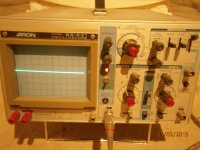
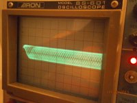
Aron BS601 oscilloscope
It is only a 20mhz scope and I hope it is adequate. Although it is an oldie it looked clean and well maintained. Only time will tell if it is worth the $60 I paid for it - including probes.
It is only a 20mhz scope and I hope it is adequate. Although it is an oldie it looked clean and well maintained. Only time will tell if it is worth the $60 I paid for it - including probes.
Attachments
I managed to do a calibration test and got a nice square sine wave, dont know it that is anything worth mentioning. Now trying components tests but not successful yet.
The calibration signal should be square. It should go up by the same distance, and for the same time, as it goes down.
A sine is a sine...if it were square the world would be very strange

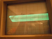
That looks pretty decent as such. I'm not sure what the amplitude is as you would need to check the scope calibration, and make sure any variable attenuators on the V/DIV control are in the "CAL" position (those inner red controls).
So when the audio drops out I'm guessing you don't see any change in the RF ?
So when the audio drops out I'm guessing you don't see any change in the RF ?
- Status
- This old topic is closed. If you want to reopen this topic, contact a moderator using the "Report Post" button.
- Home
- Source & Line
- Digital Source
- CD63KI problems - please help