hello guys!
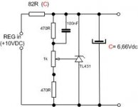
i have a questino. few days ago I made TDA1543/CS8412 DAC. Powe supply on my DAC (TDA chip) is like in picture. I tought that I would be able to set the voltage on my TDA but it is not working. Only if I chenge the 82R the voltage is going up or down. Is this o.k. or I made it wrong?
Maybe it is stupid question but ...
Attachments
Check this post:
http://www.diyaudio.com/forums/showthread.php?s=&postid=111229&highlight=#post111229
(The attachment is what you need)")
http://www.diyaudio.com/forums/showthread.php?s=&postid=111229&highlight=#post111229
(The attachment is what you need)

Konnichiwa,
You made a fundamental mistake.
The TDA1543 draws around 60 - 80mA Per chip @ 5V, more at higher voltages. If you are dropping 5V across your series resistor and you have 120mA Flowing (60mA in the DAC & 60mA in Shunt) you resistor needs to be around 39R, not 82R. For 6.66V & 160mA the series resistor should be around 22R.
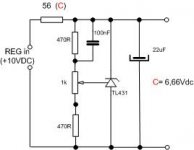
Also, you might consider changing the 100nF Capacitor to a 22uF or larger value one (recommended Sanyo Os-Con SH Series) and to connect it directly to the Pot's wiper. The load capacitor should also be Os-Con SH 22uF.
Sayonara
sparkle said:
few days ago I made TDA1543/CS8412 DAC. Powe supply on my DAC (TDA chip) is like in picture. I tought that I would be able to set the voltage on my TDA but it is not working. Only if I chenge the 82R the voltage is going up or down. Is this o.k. or I made it wrong?
You made a fundamental mistake.
The TDA1543 draws around 60 - 80mA Per chip @ 5V, more at higher voltages. If you are dropping 5V across your series resistor and you have 120mA Flowing (60mA in the DAC & 60mA in Shunt) you resistor needs to be around 39R, not 82R. For 6.66V & 160mA the series resistor should be around 22R.
Also, you might consider changing the 100nF Capacitor to a 22uF or larger value one (recommended Sanyo Os-Con SH Series) and to connect it directly to the Pot's wiper. The load capacitor should also be Os-Con SH 22uF.
Sayonara
mr wang
thanx I see it now- i guess i need that
I have tought before to connect that 100nF cap to pot's wiper but also tought that larger value would be to high. i will try to put 22uF. my output cap (one with no value on the picture) is 22uF ELNA.
I tought that my TL431 is not working right because the sound was not good.
thanx guys
Re: mr wang
Konnichiwa,
No, you need a value large enough to "couple" the AC signal on the rail into a 1K impedance. Now 22uF/1k is equivalent to a 7Hz -3db point or a rise of the dynamic impedance to around 1.414 the value per datasheet compared to higher frequencies.
Make sure it has an ESR of around 0.15R and is well bypassed. I prefer Sanyo Os Con SH Series over most other Cap's simply because more like a capacitor at high frequencies than most other elcap's.
It is not working. There is no current left for it to work with....
Sayonara
Konnichiwa,
sparkle said:
I have tought before to connect that 100nF cap to pot's wiper but also tought that larger value would be to high.
No, you need a value large enough to "couple" the AC signal on the rail into a 1K impedance. Now 22uF/1k is equivalent to a 7Hz -3db point or a rise of the dynamic impedance to around 1.414 the value per datasheet compared to higher frequencies.
sparkle said:
my output cap (one with no value on the picture) is 22uF ELNA.
Make sure it has an ESR of around 0.15R and is well bypassed. I prefer Sanyo Os Con SH Series over most other Cap's simply because more like a capacitor at high frequencies than most other elcap's.
sparkle said:
I tought that my TL431 is not working right because the sound was not good.
It is not working. There is no current left for it to work with....
Sayonara
thanx
Dear mr. Wang- thanx
You were very helpful. I connected everything like in the picture. I will turn resistor 56R (I am working on 6,0V output voltage now) further down and connect 22uF capacitor on the 100nF. Only 100nF would be connected like You said ( pot's wiper and resistor)- I have no time yesterday to do more changes - but the good news is that TL431 is working allready and I can hear it to. After I did that I put an Riken resistors on I/V an ref. and tantal resistor on output to gnd. Also I have 0,1uF russian silver PiO in parralel with 4,4uF MKP from Rifa. It is working like - VEEERY good.
Thanx guys
daniel
Dear mr. Wang- thanx
You were very helpful. I connected everything like in the picture. I will turn resistor 56R (I am working on 6,0V output voltage now) further down and connect 22uF capacitor on the 100nF. Only 100nF would be connected like You said ( pot's wiper and resistor)- I have no time yesterday to do more changes - but the good news is that TL431 is working allready and I can hear it to. After I did that I put an Riken resistors on I/V an ref. and tantal resistor on output to gnd. Also I have 0,1uF russian silver PiO in parralel with 4,4uF MKP from Rifa. It is working like
- VEEERY good.Thanx guys
daniel
Attachments
If you look at the datasheet for TL431 you'll find that the device has a pole at 8 kHz. It makes sense to compensate for this pole by creating a zero in the feedback on that same frequency. This is done by the 100 nF cap. If the zero is at too low a frequency the feedbackloop may become less stable and show some ringing on transients.
In this case I would use a 15-18 nF cap. Combined with the 1200 ohm feedback resistor puts the zero in the right place.
In this case I would use a 15-18 nF cap. Combined with the 1200 ohm feedback resistor puts the zero in the right place.
- Status
- This old topic is closed. If you want to reopen this topic, contact a moderator using the "Report Post" button.
- Home
- Source & Line
- Digital Source
- Tl431