Based on so many hi-end makers going totally digital, and I believe Linn has been using all digital for a number of years, I thought a 32 bit quality DAC (digital to analog converter) would be comparable to pure analog. If not why are so many quality components using DACs?
Thanks,
henry
Thanks,
henry
By the way, Oppo itself have renounced to this advanced digital volume control in their "high end" device HA-1. This device is have the same DAC chip inside, its volume is set it to fixed (by firmware), and the volume control is pure analogue (remotely controlled also).
Else the digital volume control it offer a particular convenience for designers, when about the many opportunities to control it by software, or integrating it in a more complex digital processing, and so on...
We may not mix the DAC principle of signal processing, and this particular part of the process, the digital volume control. These are two different subjects/discussions... While a DAC component it is able to produce a very high signal quality on its outputs (as this Sabre chip also) the volume digital controlled section of this process it may not be just perfect. This imperfection it come from the simple fact that the resolution used in such process (the number of bits) it is limited, or may not be enough (per today`s technology) to keep that 100% of the original signal integrity... There is always about an approximation there, to simulate the digital volume function of an analogue one...
Last edited:
I read the OPPO site's description of the HA-1 and all I can say is WOW. However, I don't think it would make sense to use it as a preamp, for my BDP-95, because the signal would go through the Sabre DACs in both components and then to the analog potentiometer in the HA-1. I just feel the less things in the signal path the better.
A DAC component it convert the digital data streams into analogue audio signals. The BDP 95 it output audio signals, and these are to be amplified/preamplified further, and eventual volume controlled by the devices these 95 outputs are connected to, or by the integrated into the DAC chip, digital volume controller. So these analogue audio signals, it can not, and it have no any meaning to go through a DAC component into the HA-1, if such it will be connected to a 95 BD player.
Sorry, I presume you misunderstood a little bit how in fact it works all about.
The HA-1 device it contain few different stages: a DAC system, a analogue input stage, a preamplifier stage, a analogue volume control (motorised potentiometer), and a class A headphone amplifier. What is going into this (or whatever similar) device, as analogue signals it have nothing to do with the DAC stage/component. The DAC output analogue signals, and the another analogue signals on the device`s analogue inputs, are switchable sources, which are preamplified further, and outputted on the device outputs. Into this chain there is included the analogue volume controller (the DAC stage it output always to its max/fixed volume).
In the 95 player, the DAC is the only component which it produce analogue audio signals, outputted on the device (only) analogue outputs. Therefore the integrated digital volume control into the DAC chip it is used to control the volume of the analogue signals.
Oppo have appreciated/concluded later on, that it may be a better quality for audio signals, out of a audio higher quality product, if the digital volume control it may not be controlled digitally by the DAC chip, but just using a simple analogue volume control. They implemented such approach in their next developed high end product, HA-1. In addition, they used also a class A amplifier, to increase even more the quality of their device.
That`s it, in an a quite simple/succinct explanation..
Last edited:
Thanks for the reply but I did understand that OPPO choose to send the signal out through an analogue potentiometer. I also read about it's class A amp and use for headphones or/and as a preamp. I was impressed by it's qualities and that's why I wrote WOW.
The only point, I was trying to make in my post, was that I didn't see the value of the audio signal going through Sabre DACs in the BPD-95, then the Sabre DACs in the HA-1, then through the HA-1 analogue pot.
With my OPPO set to max volume, and connected to my Audible Illusions preamp, I bascially have a simialar signal path...Sabre DACs through preamp analogue potentiometers.
I'm still going to do some comparison listening with OPPO direct to amp versus OPPO through the AI preamp. Based on OPPO's responses I don't expect to hear much if any sonic difference. Time will tell.
Thanks,
henry
I have an Oppo 105D. I had it connected analog to a Yamaha 3067 A/V receiver with a power amp. It sounded good.
I then tried it directly in to my power amp, using the built in volume control. I felt that dynamics and details improved, but fun-factcor and bass was quite a step down.
I then bought a high end pre amp, and now I have best of both worlds, with even more details and dynamics and VASTLY improved bass and fun-factor.
All right!
Changing the filtering caps it bring an improvement of course. In case this Oppo device, there is important to use some larger capacities for filtering, as the original ones are insufficient to ensure a good filtering (lowest ripple).
When about regulators for analogue stage, the original one are good for the job to be done. The problem is the filtering, and some design issues, but not the regulators itself, as components. Else, there is not so efficient to use ultra low noise regulators in that place where the original one are placed. F. ex. the positive regulated rail it is used to power the mute relays on board, and it is a little bit stupid to use good quality regulators for such task... Here is the concept itself which is not very fortunate for the Oppo design. The whole clue about low noise regulated power is to be used for the targeted circuits/stages, locally, but not for all what is on the board. Therefore I found finally out that it is a better solution to redesign the whole output stage of this player, implementing so in a better way both circuits and components. In my output module I have ultra low noise regulators for each opamp in that stage, with solid filtering. In this way the power quality for the targeted circuits (locally) it not depend very much by the rest of the power rails quality. I still use the original regulators also...
In your case, it is a good improvement to use larger capacities caps for filtering, for the components as it are. You should also improve the capacities on the opamp decoupling (caps around the opamps - power stage).
There is an improvement of course if you may bypass the AC coupling caps with film ones. Into 1µ is a good choice. Also more than 16v is not necessary in that place. Else the caps may become quite big as dimensions, and long components legs or wires for connections it may not be a good thing...
Thanks Coris. Have anyone every try Duelund Silver Bypass? I am thinking 0.01uf. Is this enough to change the color?
I recently modified an 103 model, and more than replacing the SMPS with a LPM and the standard clocks by my battery powered clock board, I thought to use a forced ventilation for the main processor. In this way the main processor (usually running at 45-50 deg.C) it run always at room temperature. The fan (through its mechanical mounting, as its low speed), is totally inaudible. The fan itself is however a low noise one...
The 103 models are very suitable for a forced ventilation, as these models it have enough space over the main processor. It is true that the 103 models do not have perforations in the enclosure, but creating a airflow inside the closed chassis, the heat transfer with the exterior it become however much more efficient.
My LPM designed for 105 models it already include an adjustable regulator stage special designated for a cooling fan. Now this stage it can be used for forced ventilation in 103 model too.
As I pointed before in many circumstances, lowering the processor working temperature it improve a lot its capabilities for a very high quality video signal. The results are really astonishing for picture. Both contrast, luminosity, tones gradients and colours are improved so. A general and very noticeable improvement.
The 103 models it can benefit much more of this improvements, as the available space inside the chassis it allow this mod much more easy. Lowering dramatically the processor working temperature in 105/105D models it can bring the same improvements for video signals, but this task it is a little bit more difficult to be realized, because a quite compact and full enclosure for these models.
Is there a fan you would recommend for this?
This is maybe not relevant, but in my DIY speakers I use Seas 27 TDFC in Seos waveguides with only a single cap in series as filtering.
And I find there is a huge sonic difference in capacitors. Since the value I use is pretty small (3,3uF) I have bought and tried several different types, including Duelund Cast Cu pio, Mundorf silver/oil and Jupiter Copper/foil/wax.
And I find there is a huge sonic difference in capacitors. Since the value I use is pretty small (3,3uF) I have bought and tried several different types, including Duelund Cast Cu pio, Mundorf silver/oil and Jupiter Copper/foil/wax.
Is there a fan you would recommend for this?
I do not have a selected brand for a such fan. At least one should not use the ball bearing based fans. As these cooling fans are extremely cheap today (Chinese produced ones). one can buy may of it, and then select the lowest noise one to be used. I did/do so with very good results.
For 103 models the available circuit to power this fan (synchronous power on), does not exist. So this it should be (re)implemented. A small modification it is necessary on the main board (in case of using my LPM). Else, an alternative solution it is using the USB power from one of the device ports, which it is up at power on. However, this USB power is a fixed one (5v), and therefore does not allow speed adjustment.
For these reasons, I implemented in my LPM a dedicated stage for fan control, but this stage it can not work for 103 models, without the modification mentioned above (main board). A speed control for a such fan is important, as the produced airflow it have to be controlled for a efficient ventilation.
One may note also that the most of the cooling fans out there are produced based on a (included) switching circuit, which it control the small motor`s windings, quite precisely. This approach it lower the audible noises, and vibrations, but it create a electrical noise, transmitted further through the power system.
So, both the fan and its power control device it have to be corrected for this issue... The fan section in my LPM it is designed accordingly, to minimise both the audible, and electrical noises. Also my mounting approach for a cooling fan it prevent completely any of the mechanical vibrations to be transmitted further to the chassis. The overall result: a completely noiseless and very efficient forced ventilation...
This is maybe not relevant, but in my DIY speakers I use Seas 27 TDFC in Seos waveguides with only a single cap in series as filtering.
And I find there is a huge sonic difference in capacitors. Since the value I use is pretty small (3,3uF) I have bought and tried several different types, including Duelund Cast Cu pio, Mundorf silver/oil and Jupiter Copper/foil/wax.
So what differences do you find between them and which one do you prefer ?
Thanks.
The Mundorf's I find extremely detailed, but a bit cold and lacking a bit of "body". The Duelund's are at the opposite side of the scale, being extremely warm and a lot of "body". The Jupiter I find being somwhere in between, and this is my favorite for my system. But what I guess is that you can "tune" the sonic character to match the rest of your system.
In a perfect world I would have used Duelund for mids, Jupiter for tweeter and Mundorf for super tweeter..M.
In a perfect world I would have used Duelund for mids, Jupiter for tweeter and Mundorf for super tweeter..M.
The initial subject (previous asked question) it was about using Duelund or différent other caps in this Oppo device ("Oppo`s BDP105 - discussions, upgrading, mods..."), but not for tweeters, speakers, or other components of a system. Which obviously, it is not just the right subject for this thread...
Last edited:
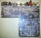
Having a 105D main board on my bench, I took a closer look at the clock system on board. There is hereby a picture of the clocks distribution for the different stages. The 12Mhz clock on board is designated for the USB responsable chip. This clock it is not important for improvements purposes, so let`s ignore it.
All the clocks are internally generated by these chips, based on resonators, except the Darbee processor, which it have a 54Mhz oscillator. As I can see Oppo designers cared a little bit more for the Darbee clock circuit. A ferrite bad it filter first the power for this oscillator, then three different values/types caps, are used as filters, after the ferrite bad. The Darbee processor is AC coupled to the oscillator output. Comparing this clock approach used for Darbee chip with the rest of the main chips, it seems that the quality of the clock signal for Darbee processor it may be quite critical.
Another observation I have is the physical dimensions for Oppo main processor and the Darbee one. The main processor it have two HDMI channels, and is smaller than the Darbee one, which is meant to process only one HDMI channel. Taking the dimensions of the chips as a criteria, one may conclude that the Darbee processor is a lot more powerful and extreme complexe, while the Oppo main processor is smaller, even though it have to manage with two HDMI outputs, and the whole rest of the device control, memory controller, audio decoding, and so on...
My main thought is in this respect is to unify all these clocks spread over the whole board, as their frequencies it show it is possible to have only one oscillator as master clock, then divided accordingly to obtain the necessary clock signals for the targeted chips. I appreciate that I may have a quite good solution for such modification/improvement. I have already a 216Mhz Epson SAW oscillator, and the divider I also use together with my battery powered clock board. I think I will give it a try to clock the whole device from only one 216Mhz oscillator, including the DAC chip...
Attachments
Last edited:
I do not have a selected brand for a such fan. At least one should not use the ball bearing based fans. As these cooling fans are extremely cheap today (Chinese produced ones). one can buy may of it, and then select the lowest noise one to be used. I did/do so with very good results.
For 103 models the available circuit to power this fan (synchronous power on), does not exist. So this it should be (re)implemented. A small modification it is necessary on the main board (in case of using my LPM). Else, an alternative solution it is using the USB power from one of the device ports, which it is up at power on. However, this USB power is a fixed one (5v), and therefore does not allow speed adjustment.
For these reasons, I implemented in my LPM a dedicated stage for fan control, but this stage it can not work for 103 models, without the modification mentioned above (main board). A speed control for a such fan is important, as the produced airflow it have to be controlled for a efficient ventilation.
One may note also that the most of the cooling fans out there are produced based on a (included) switching circuit, which it control the small motor`s windings, quite precisely. This approach it lower the audible noises, and vibrations, but it create a electrical noise, transmitted further through the power system.
So, both the fan and its power control device it have to be corrected for this issue... The fan section in my LPM it is designed accordingly, to minimise both the audible, and electrical noises. Also my mounting approach for a cooling fan it prevent completely any of the mechanical vibrations to be transmitted further to the chassis. The overall result: a completely noiseless and very efficient forced ventilation...
I have lots of adjustable power supplies (and resistors) I can use to power a fan externally. I am sure I can thread the wire inside the 103. Just need to find the right fan size.
I have lots of adjustable power supplies (and resistors) I can use to power a fan externally. I am sure I can thread the wire inside the 103. Just need to find the right fan size.
Well, there is all right. An appropriate fan size it is 70-80mm diameter. As larger the diameter, as bigger the amount of air moved at a even lower speed. However, a too big diameter is not very reasonable, at it complicate the mounting approach. The better fans for this task are the ones without frame around the propell.
There are made also low voltages fans out there, but I will recommend using the 12v ones, powered at around 5v. Doing so it decrease much their audible noises. Please keep in mind that the airflow speed for a efficient ventilation is very low. As the airflow generated it is too strong, then turbulences occur and the ventilation efficiency it decrease very much. The principle here is to remove the heat developed around a heatsink in a closed environment, and for this tasks it is enough an extremely low airflow over that heatsink. Well, in case of an enough reduced heat generating (50-60 dec. C). Also there are necessary some experiments and results appreciations for the particular case...
Of course one can use a lot of PSUs types to make spin a fan, but in this case of an audio device, some precautions it may be taken, to not worse the overall performances of the host device. There are excluded in this case the SMPS type to power a fan. Also an important detail is to synchronise the power on/off sequences between the fan end the host device. There is no any clue to have a fan spinning all the time inside a device. At least such approach it can do more damages than good (it can increase the temperature differences for the components to be cooled, and increase their thermal stress).
I may suggest at least the use of the USB port power (which is synchro power on/off), and adjust it for the right speed of a 12v fan, in case it can produce noises at the 5v. As usually it work fine without adjustments. Also the fan mounting is crucial to prevent vibrations to be transmitted through the chassis (the very cheap fans on marked are quite bad mechanically manufactured, and vibrate a lot). This is a very audible side effect of a forced cooling...
Some experiments are necessary... Good luck!
")
Last edited:
I can also suggest this procedure to select/chose the right fan (lowest audible noise):
Find a potentiometer adjustable PSU (12v), to power your chosen fan device.
Mount that fan (on a bench) in a similar way you will mount it in place inside the Oppo enclosure (an elastic/damping mounting however). Power the fan at its max speed/voltage, listening closely its audible noise. Decrease progressively the voltage of the PSU, so to find/hear the less audible noise as possible out of that fan. You will observe that are many points in this adjustment, where the fan it resonate, vibrate in a particular maner, producing noises more or less, and so on. When you find its most quest spinning speed, note the voltage and then use that (appropriate resistor) for a finial mounting/powering approach.
Last edited:
I can also suggest this procedure to select/chose the right fan (lowest audible noise):
Find a potentiometer adjustable PSU (12v), to power your chosen fan device.
Mount that fan (on a bench) in a similar way you will mount it in place inside the Oppo enclosure (an elastic/damping mounting however). Power the fan at its max speed/voltage, listening closely its audible noise. Decrease progressively the voltage of the PSU, so to find/hear the less audible noise as possible out of that fan. You will observe that are many points in this adjustment, where the fan it resonate, vibrate in a particular maner, producing noises more or less, and so on. When you find its most quest spinning speed, note the voltage and then use that (appropriate resistor) for a finial mounting/powering approach.
Yes, that was my plan
The body of the component itself it can come up to 70deg.C, on a max load of 5A. This is a very max load, which is a little bit higher than an Oppo device it use (up to 4 A with two USB ports loaded with hard disks). Else on a average load inside the player (105) it can come up to 55 deg.C. Inside a 105D model, as the power demand is a little bit lower, because the latest processor version, the LPM`s load is even lower.
On a normal use of the player (+ one USB port), the temperature of the LT1083 (body) is approx 50 deg. C. The center of the LPM heatsink it still around 45deg.C. These may be the normal thermal parameters... There are actually the USB ports which it can load quite much the 5v rail of this LPM, especially when a spinning hard disc is connected to the player. Therefore I will suggest to not keep connected a such consumer on USB ports, if it may not be in use.
One should not be worry about the regulator temperature. The component is thermal protected, as over current protected too.
As my new version LPM it dissipate through the device chassis, an important amount of the heat it is exhausted this way. However, as the chassis is made of steel, its capability to transmit the heat to the environment is enough limited. Therefore I advise the use of a fan inside the enclosure (as described previously in this thread). Such fan it make the air inside to circulate, providing a better temperature exchange, for all the dissipating components inside, including the LPM (which however it spread an amount of its heat inside too).
Last edited:
- Home
- Source & Line
- Digital Source
- Oppo's BDP105 - discussions, upgrading, mods...