SMPS vs Serial PSU
Coming back with some more infos and comparing the Oppo SMPS with a serial PSU.
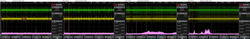
I have to say first that both these power supplies was previously extended improved, before the measurements was taken. The SMPS it got supplementary filtering cells for both 5v and 15v rails, as many other improvements to minimise the HF output noises. The serial PSU was in this case a Oppomod one, also quite extended improved. This PSU is enough bad designed when about the PCB layout. So, one have to correct it quite much to get some better performances out of this PSU. The improvements also eliminate the need of an external power filter for this power supply.
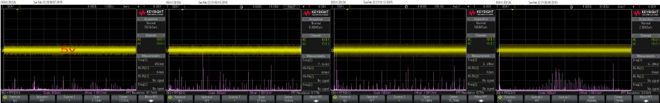
The PSUs was tested and measured with resistive loads for a medium scale current/power. Then the PSUs was connected to the real consumer: the player system. The results of measurements are to be seen here.
As one can notice at once the HF noises on the PSUs rails it increase dramatically when connecting to the digital system. Normally and enough expected, but however disappointing...
I may precise that my scope, with connected and open probe, it shows a noise level of 12mV. I suppose this level it may not decrease much when to connect the probe to the PSUs outputs. There may be enough correct to assume that a 10-12mV it may be the base level of the noises measurement for the PSUs outputs.
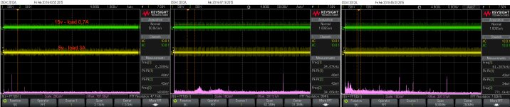
The noise performances of the serial PSU are obvious, even though connecting the PSU to the system it degrade quite much its performances.
I may precise again, that these SMPS and Serial PSU are to feed the digital stage of the device, and have almost nothing to do with the analogue stage (which it have its own transformer and power system).
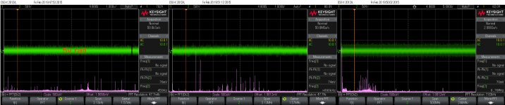
As the digital system it induce HF noises into the PSUs rails, degrading their performances, one may not expect a noticeable improvement for the resulting audio signal (sound) at the device`s outputs. Well, such expectation is only wrong.
The serial PSU it improve the resulting sound out of the player dramatically. This improvement is even more dramatic on an already improved device. In spite of what it shows the noise measurements on 5v rail of the serial PSU connected to the system, the improving for both sound and picture are obviously and quite dramatic. I have no any explanation so far about why is like this. Up to you to comment...
The main conclusion of these tests and measurements: get rid of that original SMPS, no matter it is an original one or an improved.
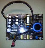
I have already started the work to design and produce a serial PSU for 105 models, because this Oppomod is quite a joke...
The heat dissipation it will be minimised as much as possible and an (included in the kit) fan it will solve the ventilation problem for the whole device. The fan is tuned so to not generate an audible noise at more than 15cm distance from it.
I do hope to come back soon for presenting my serial PSU for 105/105D models...
Coming back with some more infos and comparing the Oppo SMPS with a serial PSU.
I have to say first that both these power supplies was previously extended improved, before the measurements was taken. The SMPS it got supplementary filtering cells for both 5v and 15v rails, as many other improvements to minimise the HF output noises. The serial PSU was in this case a Oppomod one, also quite extended improved. This PSU is enough bad designed when about the PCB layout. So, one have to correct it quite much to get some better performances out of this PSU. The improvements also eliminate the need of an external power filter for this power supply.
The PSUs was tested and measured with resistive loads for a medium scale current/power. Then the PSUs was connected to the real consumer: the player system. The results of measurements are to be seen here.
As one can notice at once the HF noises on the PSUs rails it increase dramatically when connecting to the digital system. Normally and enough expected, but however disappointing...
I may precise that my scope, with connected and open probe, it shows a noise level of 12mV. I suppose this level it may not decrease much when to connect the probe to the PSUs outputs. There may be enough correct to assume that a 10-12mV it may be the base level of the noises measurement for the PSUs outputs.
The noise performances of the serial PSU are obvious, even though connecting the PSU to the system it degrade quite much its performances.
I may precise again, that these SMPS and Serial PSU are to feed the digital stage of the device, and have almost nothing to do with the analogue stage (which it have its own transformer and power system).
As the digital system it induce HF noises into the PSUs rails, degrading their performances, one may not expect a noticeable improvement for the resulting audio signal (sound) at the device`s outputs. Well, such expectation is only wrong.
The serial PSU it improve the resulting sound out of the player dramatically. This improvement is even more dramatic on an already improved device. In spite of what it shows the noise measurements on 5v rail of the serial PSU connected to the system, the improving for both sound and picture are obviously and quite dramatic. I have no any explanation so far about why is like this. Up to you to comment...
The main conclusion of these tests and measurements: get rid of that original SMPS, no matter it is an original one or an improved.
I have already started the work to design and produce a serial PSU for 105 models, because this Oppomod is quite a joke...
The heat dissipation it will be minimised as much as possible and an (included in the kit) fan it will solve the ventilation problem for the whole device. The fan is tuned so to not generate an audible noise at more than 15cm distance from it.
I do hope to come back soon for presenting my serial PSU for 105/105D models...
Attachments
-
 Original SMPS with improved final cap filtering.jpg696.8 KB · Views: 356
 -
 SMPS - extended improvements - resistive loads.jpg750.3 KB · Views: 337
 -
 SMPS improved - connected to the system.jpg635.5 KB · Views: 312
 -
 Serial PSU resistive loaded.jpg694.7 KB · Views: 287
 -
 Serial PSU connected to the system - 5v rail.jpg643.1 KB · Views: 290
BDP105/105D it have a SMPS for digital stage, and an analogue (serial) PSU for the analogue stage of the player (stereo and multichannel boards, including DACs power rails).
If you open the box beside the Oppo transformer, there you will find the SMPS... To preciselly answer to your question: the SMPS it come from Oppo...
BTW, the digital stage of the player (main processor and adjacent circuits) it need few amperes tu run. The toroid and its regulators it can not deliver so much current to power the whole device. That because the power system is divided in two parts: one for digital and another one for analogue.
Last edited:
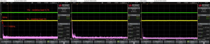
The noise of the analogue power system it consist mainly of the 100hz ripple. But a 50hz ripple (or component of it) is to be founded right into AVCC regulator (DACs).
That because an important improvement/mod for this player is to replace/improve the most of the filtering caps involved in the serial power system.
I have measured these lines too, but I did not archived these measurements for an presentation... There is enough to replace the filtering caps to improve a lot the noise (ripple) level for analogue stage.
Last edited:

Oppomod LPM
I see that there is a lot of discussion of the Oppomod linear power module.
I purchased this device about one year ago and and installed it in my oppo-105.
I posted my observations at that time on this thread, but here's a follow-up.
First of all, I'm very happy with this power supply. It has substantially improved my audio system. In particular, after installation I noticed a more relaxed quality to the music. The power supply is not inexpensive, but it is very convenient, and also easy to install.
When I installed my unit, I did add some heat sink compound between the bottom of the heatsink and the lower chassis. This improved the thermal conduction between the heatsinks and the outside world. I also removed the central one third of a cross strut that is partially in the way. I've always noticed the unit to run cool, perhaps even cooler than the original power supply. There is no need for a fan.
I would say that the unit is built and designed to the task, in other words it is simple but works well. It is interesting that Coris observed significant pass-through of high-frequency noise from the AC power. I note that I have always used numerous external power supply filters, and recommend these both to Coris and others. However, I also agree with his suggestion that adding AC filtration at this point is desirable.
I should add that one limitation of this unit is that the oppo player will now require input voltages of at least 110 VAC. During the summertime here we often get low-power conditions with power sometimes dipping to 108 VAC. One solution to this problem is to purchase the higher end linear power module produced by Oppomod . This unit uses higher-quality capacitors, and Schottky diodes with reduced voltage drop.
I ultimately decided to purchase a PS audio powerplant premiere AC power regenerator to power my entire system. My system was sounding wonderful at night, but not as good during the day. I knew from experience and also measurement that my AC power was very dirty, often had DC offsets, and also had significant distortion and flat topping. Passive AC line filters can only go so far. So for me the purchase of the PPP has really been incredible. This improved the sound of my system, but also it now always sounds its best. I only wish that I'd been able to afford one of these units years ago. This also outputs a steady 118 VAC. In any case I very strongly recommend one of these units if you do not have excellent AC power. (The unit indicates that my incoming AC has 8.5% distortion day and night).
In summary, I agree that it is very desirable to replace the SMPS with a linear power supply. I also recommend a lot of attention to incoming power quality.
Eric
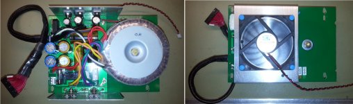
Well, I`m a little bit sceptic about the design of this LPM unit, after I have examined in details and measured it. It is "designed" to support and deliver few DC amperes, and the PCB traces are quite thin dimensioned for such currents. The ground connections between components are quite chaotic placed/designed, but it make the connections at least... The lack of some components in the design it make it vulnerable to HF noises (pass through).
These only few named layout issues leads to an increased ripple on its outputs... Its noise on outputs is about more than 60 mV as it is (3A loaded on 5v)... This is very much for a serial PSU. After improving and correcting the layout, as some components, the noise get so low as 16mV.
I also doubt very much about the efficiency of the original heat sinks of this Oppomod, but however the high heat dissipation of this serial PSU inside an passive ventilated enclosure is a serious issue. I have placed the improved LPM with the fan on it as you can see in the above pictures, into the player (with removed multichannel board). With the fan activated over the LPM heat sink, and after two hours functioning, I`ve measured the temperature of the DAC chip, as 52-54 dg. C. the heat over the stereo board area was well noticeable through the upper cover... The LPM heat sink measured around 40 dg. C.
The conclusion here is: in such approach, the LPM was well ventilated and its heat was not spread into the rest of the enclosure. But the rest of the enclosure was so poor ventilated as the components temperature increased enough high.
After these simple observations I just wonder when somebody state that is no need for a forced ventilation with this LPM inside the player... BTW, the SMPS do not dissipate anything heat even loaded with 5A...
I have removed the fan from the place over the improved LPM and placed it so to create a air flow inside the enclosure, with cold air admission from the main/stereo board area and directed to the LPM place on other side of the device. The effect of this approach was huge: DAC chip was running after many hours at 42dg.C, the processor temperature decreased also dramatically, the entire area of the boards was at the room temperature, while the LPM heat sink it measured 47dg.C, and is very easy to notice that the heat is exhausted only in the LPM area.
Sorry, but I can not trust very much the idea that an LPM inside the player enclosure do not need a forced ventilation. Well, one may ignore this detail, but then the player`s components it run at quite high temperature. Is this good and safe for the device parameters, or its life time? I seriously doubt...
Last edited:
Sorry, I do not fully get it about your assertion/logic...
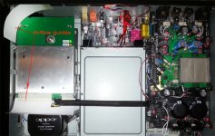
I was thinking the multichannel board it have another function than ground plane or shield for the rest of the boards inside... The multichannel board`s place is on the same level with the stereo board. BTW, the upper steel cover is removed only to make possible the picturing...
The stereo board it have already at least one ground plane inside it, as some external good ground plane areas. There are also at least three another ground planes in between, which it separate my analogue stage (green boards), from the rest of the boards. The most sensitive part of my output module it is already well shielded (not to be seen in the picture). Absolutely no what so ever shielding problem here. The most noisy field of the main board is supposed to be the small SMPS area, which are to be found under the power stage of the stereo board. However, this area do not radiate so far to induce noises into the analogue PSU upstairs...
No any worries about this aspect. But if you may suppose that the "radiations" it may follow the airflow created by the fan, then well, you may have right...
Last edited:
When the multichannel board is in place, it is grounded and this acts to form a ground plane or part of a ground box around the mainboard with its digital electronics. This shields to some extent the analog board.
I have run the machine with and without this board in place and for me there is a noticeable difference.
Therefore I leave it in place and grounded although I'm not using it.
I was suggesting that you might also want to have a ground plane in this location even if you're not using the multichannel board.
Eric
Thanks for your further/extended explanations. But I can hardly agree with...
I can not deny your experiences with/without the multichannel board in place.
We may note that in this particular case, there is not about the original design for the analogue stage. This is completely dismissed on the original stereo board. It is used only the DAC chip in its original place, but some of its connections are dismissed too (AVCC, VddL/R, as some of its output channels traces).
Maybe when about the original design one may observe some difference, even though I strongly doubt. As you can see my output module it have a much smaller areal than the original post DAC processing stage design. Its capabilities to capture environmental EMI noises is extremely reduced, especially for this environment.
The fully differential circuits (which are by definition strongly immune to noises) on this 4 layers design module, are protected by its two internal ground planes. In addition, the sensitive circuits are protected by a steel plate shielding on its back side. As the opamps are individual shielded (see picture). Under this module it are another two ground planes of the module`s motherboard. Under this assembly (output module + its motherboard) there are at least the another two ground planes of the original stereo board. This analogue assembly it is placed at least 60mm over the ("noisy") digital board. Right under this area of the stereo board, it is placed the main processor. This processor is cooled by a heat sink which is grounded (my approach, but not Oppo`s...). The video chip it is also grounded on its heat sink (my own approach too). The most of the digital chips are covered (customer his approach), by EMI protective material.
I can fully assure you that in this device (not to be seen in this picture) there are lot of shielding everywhere in the right places. There is absolutely no any chance for a such statement, of shielding issues in this case, even without the multichannel in place.
But I can agree that for some mystical reasons it may appear some issues/differences with/without the ground planes of the multichannel board in its place. If is the case (as you tell about) with an original device, then it may be another design issue. This is a very unusual behaviour, and such should be eliminated in the earlier stages of the developing process for this device...
After you will have implemented few or all of the modifications/improvements to be seen in the above picture, I can guarantee you that you will never observe such differences with/without the multichannel board in the field. This is very easy to be demonstrated: just send me your boards for fixing...
Last edited:
- Home
- Source & Line
- Digital Source
- Oppo's BDP105 - discussions, upgrading, mods...