A new Oppo player is on the way to marked.
This thread is meant to facilitate discussions and ideas changing about BDP105 player, about eventual upgrades, and modifications.
Oppo has come out with only few pictures of the boards of BDP105.
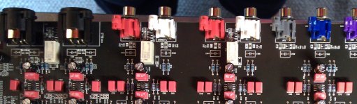
A preliminary examination of the inside pictures it shows that Oppo used a high performing chip op amp for headphone stage. This chip can run up to 2-3W, so is not any problem to drive the most of the headphones. The lowest driving impedance of this op amp is 8 ohm. One can see the placement of this stage on the analogue board here by. It looks to me that the headphone op amp is DC coupled to the output (through resistors)... I`m almost sure now that all the other outputs of the BDP105 are AC coupled. It seems that is planted a large capacitor on the signal output path on each channel! This surprising me very much, and I think is very unfortunate...
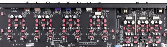
It seems to me that the DAC chip itself is used in a different way than in the earlier model (95). A short clarification about the ESS9018 DAC chip: this chip have 8 independent DAC channels inside. Those channels can be connected (hardware) together (2, 4, 6, 8) When all the 8 channels are connected in parallel (for only one stereo channel), one have the max accuracy of the resulting signal. 8 DACs working together and output the same signal (one may use two ESS9018 to have a LR stereo in such case). In stereo configuration of one DAC, are used 4 + 4 channels connected together for max accuracy. Multichannel configuration use all the 8 channels independently.
In the BDP 95 model, the stereo output were obtained from 4 + 4 channels (4 channels connected together). This assured max accuracy for the stereo signal in BDP95 model. In the upcoming BDP105 it seems that Oppo used a configuration for ESS9018 which assure 2+2 channels for balanced/unbalanced output, and 2+2 channels for headphone output. I`m not very sure about the allocation is strictly in this way, but is very sure to me that the Sabre chip is hardware divided between RCA/XLR output and headphone output.
Personally I`m quite critic to this design. I should want that one could have the possibility to use 4+4 channels of the chip for both (switching) normal out and headphone out. This way could assure the max accuracy in both cases. When one use the headphone is no any reason to have half part of the DAC chip hardware dedicated to another output which is not in use, and opposite. This judgement is made as a consequence of what is to be seen in the high resolution inside picture of 105 model. Oppo are welcome to correct me if I have seen wrong in the picture, or to precise more on this aspect...
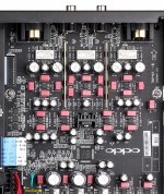
It seems that this player model have a better distribution of the analogue power supplies and regulators on the boards. Having two dedicated outputs from the toroid transformer it make the PSUs more efficient and it assure less heat dissipation inside the enclosure. This design it were already a must for the 95 model, and it looks like it is implemented now in 105 model.
This thread is meant to facilitate discussions and ideas changing about BDP105 player, about eventual upgrades, and modifications.
Oppo has come out with only few pictures of the boards of BDP105.
A preliminary examination of the inside pictures it shows that Oppo used a high performing chip op amp for headphone stage. This chip can run up to 2-3W, so is not any problem to drive the most of the headphones. The lowest driving impedance of this op amp is 8 ohm. One can see the placement of this stage on the analogue board here by. It looks to me that the headphone op amp is DC coupled to the output (through resistors)... I`m almost sure now that all the other outputs of the BDP105 are AC coupled. It seems that is planted a large capacitor on the signal output path on each channel! This surprising me very much, and I think is very unfortunate...
It seems to me that the DAC chip itself is used in a different way than in the earlier model (95). A short clarification about the ESS9018 DAC chip: this chip have 8 independent DAC channels inside. Those channels can be connected (hardware) together (2, 4, 6, 8) When all the 8 channels are connected in parallel (for only one stereo channel), one have the max accuracy of the resulting signal. 8 DACs working together and output the same signal (one may use two ESS9018 to have a LR stereo in such case). In stereo configuration of one DAC, are used 4 + 4 channels connected together for max accuracy. Multichannel configuration use all the 8 channels independently.
In the BDP 95 model, the stereo output were obtained from 4 + 4 channels (4 channels connected together). This assured max accuracy for the stereo signal in BDP95 model. In the upcoming BDP105 it seems that Oppo used a configuration for ESS9018 which assure 2+2 channels for balanced/unbalanced output, and 2+2 channels for headphone output. I`m not very sure about the allocation is strictly in this way, but is very sure to me that the Sabre chip is hardware divided between RCA/XLR output and headphone output.
Personally I`m quite critic to this design. I should want that one could have the possibility to use 4+4 channels of the chip for both (switching) normal out and headphone out. This way could assure the max accuracy in both cases. When one use the headphone is no any reason to have half part of the DAC chip hardware dedicated to another output which is not in use, and opposite. This judgement is made as a consequence of what is to be seen in the high resolution inside picture of 105 model. Oppo are welcome to correct me if I have seen wrong in the picture, or to precise more on this aspect...
It seems that this player model have a better distribution of the analogue power supplies and regulators on the boards. Having two dedicated outputs from the toroid transformer it make the PSUs more efficient and it assure less heat dissipation inside the enclosure. This design it were already a must for the 95 model, and it looks like it is implemented now in 105 model.
Yes, is about TPA6120A2. At last one may take the data sheet as reference... What is there is quite impressive... Personally I did not analysed in details this chip or measured, but I have listened though it. And it was a very good sound out of it...
Actually one may do the same in this case, but for now (without the player on place) are only observations based on pictures/documentations, and maybe speculations...
If you have better experience with this chip, then are welcome your knowledge.
We have to note that this player is not an very high end product... But an player good enough, using quite high end components for a quite reasonable price...As I see in the pictures, the design faults are not eliminated much by Oppo even we have a new and "designed from the ground up..." player. But I can not understand why they chosen AC coupling on all output of the player...
Last edited:
its not a bad chip as long as you dont follow the application note, or use it with low impedance headphones if you do. but if they have followed the datasheet spec, it is not suitable for 8ohms, not even close. you have to enclose the output resistance in the feedback loop to make it suitable, but they never do, seems designers these days just cut and paste without thinking.
you cannot just remove the series resistor, its a current feedback amp and cable capacitance really ***** with it. the datasheet calls for minimum 10ohms and up to 100ohms, thats completely out of step with modern headphones, most headphones you will find these days that are that low impedance are multidriver in ears, with high output impedance the frequency response and particularly bass response is all over the map because the impedance usually dips quite a bit lower due to the crossover.
its a well known issue for a couple of years and I cant believe yet another manufacturer has just blindly made the app note circuit and then quoted the manufacturer spec.
haha output caps you say? the output resistor is probably even bigger then, sounds like a lazy approach all round. surely with their staff they could have worked out some way to switch the outputs for headphone or line out
Last edited:
At this moment one do not know details about how Oppo has chosen to use this headphone chip. If is an 10 ohm or 100 on that output. I hope they used an 10 ohm resistor. Else is quite stupid to use 100... I think is not big problem to lower that resistor to 5 ohm if the headphone cable is not very long...
I have been experimenting with this chip one time, using it as a buffer before an amplifier (with an 300 ohm load resistor). I ware impressed by the result... Afterwords I found better ways to do it...
About this stage of the BDP|105 we will see more later ...
I have to precise that headphone out is not AC coupled. But I see in the picture (I will publish here later on) some large capacitors on the rest of all output channels of the player. It seems to me that those capacitors are on the signal path in an AC coupling design... What could be their reason(s) to do this is a very big question...
even with 5ohms with an 8ohm headphone its... its old school and covering their *** in case someone uses it with an unusually capacitive headphone cable or driver. you cant lower it really, not without a scope. with a crossover in the signal path you have more capacitance to worry about than the cable and it doesnt just effect multidrivers, with 10ohms it will effect single dynamic driver headphones up to 60-70ohms.
for higher impedance headphones (over 100ohms) its quite a good chip, reasonably powerful and clean sounding, but with low impedance and the app note design it has bass rolloff and a hump higher up. if you include the resistor in the feedback network you dont have this problem, but any time I see it by a non diyer and even some diyers and headphone lovers, theyve just copypasted the app note.
I havent looked at any pics so cant comment on the caps you speak of
Last edited:
I think I have now an explanation about why Oppo has chosen the AC coupling on all the outputs of the 105 model (if this coupling will be confirmed at last). They could not control in production process the 0v DC offset at the output of the final op amps. An 0v DC offset is very important to assure the high performance of the channels amplifiers (in an DC coupling). An high DC offset before the output capacitors, do not necessary mean that the final amplifier stages work at high parameters... and the useful audio signal which goes through the AC coupling is at very high quality one...
But everything was fine for the 95 model, where all the channels were DC coupled, and the DC offset were in acceptable low limits. The AC coupling choice for the 105 model as a solution against a high variation of the output offset, or the difficulty to control this parameter in production process, it may be a consequence of choosing another type of op amps in 105 model, than it were used for BDP95, lower quality of the passive components, or the opamps in 105 are of a lower quality/parameters ones, and of course cheaper... Both those alternatives are not something positive for Oppo and for the new/upgraded player model...
To control by design and then in production the offset of output channels for an DC coupling, it may not be a difficult task for some professional designers. The datasheet of the ESS9018 itself recommend some solutions to well control the output opamps offset. At Oppo has chosen an old fashion coupling, which is definitely a low quality one, for outputting the audio signal, it seems to me that they were forced to do so, by a bad (again) electronic design in this analogue area, or because of economic reasons (a lower quality components from an accepted provider). The economic reasons mean in this case that they want to invest less and sell the final product for more... If this hypothesis it will be true, then it may not "sound" quite well for Oppo`s reputation...
Back to the DAC channels allocation problem, and the downgrade for the 105 model (comparing to the 95 one) in stereo stage.
Oppo could proceed to a very real and effective upgrade if they should use an double DAC mono configuration (one ESS9018 for each stereo/headphone channel stage). This mean that all the 8 DAC channels will work for one of the stereo channels. In this way ESS9018 deliver the max of 133/135 dB dynamic. Such design would be very possible on the same board, and sure enough, with the same software (or very small changes). I can not see that such configuration should have a very important impact on the final price of the player. It may be in to the same 200$ over the 1000$ price of the former model... The ESS9018 chip it cost 60$ when one buy one or few chips. If a big producer as Oppo buy thousands of such DAC chip for a big production, then the price it may decrease very much. I can not see that using one DAC chip more in this new player could be a economical problem and big impact for the final price of it...
Those problems which come out in the case of the 105 model, and another ones which were for the 95 model too, an stated upgrade which it looks in real more like an downgrade (for the analogue stereo stage) in the new model, it make me a quite low impression about the electronic (analogue) design department of Oppo...
Last edited:
Here is an answer from Oppo about the DAC allocation problem in BDP105 as it is published in post 1977 in AVSForum thread (Official OPPO BDP-103/BDP-105 Anticipation Thread):
"I spoke with our engineers, and this is how the DAC works for the stereo output / headphone output:
2 channels allocated to the headphone section
2 channels allocated to XLR outputs
2 channels allocated to RCA outputs
2 channels to ground"
My only comment to the last line of this answer is: It could be anything more stupid then this kind of design...
Thanks for your detailed insights Coris.
So in terms of outright audio performance would you say that the BDP-95 is probably superior to the 105?
Which model would you find more amenable to modding/correcting of the design issues?
Even though BDP105 have already some design problems, I think it have some advantages too, over BSDP95 when about modification possibilities. It is more modular, and one do not have to handle with a very big board as in 95 model. The fan less is also another advantage. The analogue PSU it seems to be another big advantage. But I do not know much details about this new PSU in 105. I just think it may be better (the toroid transformer is already)
It may be more easy to take out all that capacitors on the outputs and realize a DC coupling (maybe it will need better final opamps...).
But it could be a problem with those DAC 2 channels which are grounded... Here will be necessary a big mod... But I`m not very sure about the firmware how will handle with those 2 grounded channels, if one will want to use it....
As a conclusion, my option will be at last the 105 model...
Last edited:
Some interesting clarifications from Oppo (published in AVForum):
Q1. What op-amps are you using in the 105? Are they the same amps used in the 95?
A1. For the BDP-105 we are using the same op-amps as the BDP-95, the LME4562.
Q2. Would you please let me know how the output ESS9018 DAC is configured for the analog stereo outputs and headphone amplifier? For the 83SE and the 95, 4 dacs were dedicated to each stereo and XLR channel for a 4+4 configuration. Is it 2+2 for the XLR channels, 1+1 for the RCA and 1+1 for the headphone amplifier channels? The concern is that the 105 will have inferior analog specs(SNR, THD etc) when compared to the excellent BDP-95.
A2. We want to ensure you that the BDP-105 has the same analog specifications and performance as the BDP-95. This has been a requirement for our design and engineering team from the very beginning of the BDP-105 project. It is also the reason for the new DAC configuration.
In the BDP-105's stereo board design, the 4 pairs of DACs in the ES9018 DAC are allocated as: 1 pair for the RCA outputs, 1 pair for the XLR outputs, and 2 pairs stacked for the headphone amplifier. We had incorrectly stated in the past that 1 DAC pair was used as a ground. This was at one time true as we were working on the engineering, but the final production model which will be shipping to customers will not use a 1 DAC pair for the ground.
During the initial design stage, we simply continued the BDP-95 approach by stacking 4 pairs of DAC for each L/R channel. However due to the complexity brought in by the newly added headphone amp and USB DAC, we could not achieve an ideal PCB layout. The analog specifications became slightly worse than the BDP-95 in this 4 stacked configuration. Our audio engineers and consultants analyzed the problem and made many experiments to further enhance the quality of the analog output stage of the BDP-105. In the end, they decided that the only way to ensure maximum performance was to separate the current-to-voltage conversion stages for each output path. This change enables us to have a much cleaner PCB layout which minimizes interference and crosstalk. It also eliminates the possibility of the load on one output path affecting the other paths. The drawback is that we now lose the benefit of the thermal noise cancellation by stacking 4 DACs. The engineers were able to make up for that by designing an improved power supply, optimizing the filter and drive stages, and beefing up the power and ground paths. The new design costs more than the BDP-95's stereo outputs so it is absolutely not a cost cutting measure. We end up using more high performance components such as op-amps, WIMA and ELNA capacitors.
We try to give conservative, nominal specifications in any literature that we produce, even when the player is known to exceed them. We list the BDP-95's THD+N as -110dB. In our own test it was -114dB. The BDP-105's THD+N is also listed as -110dB. In our own test it was between -115 or -116dB, slightly better than the BDP-95.
The headphone amplifier gets 2 pairs of DAC because its load is much higher than line-level RCA and XLR outputs.
Q3. Are the BDP-105 analog outputs AC or DC coupled? The 95 and 83SE outputs were DC coupled. If the 105 outputs are AC coupled, can you tell us why this is the case?
A3. The BDP-105 analog outputs are AC coupled. The BDP-95 used DC coupled output, and we have had a few rare but annoying compatibility issues with certain amplifiers. Some amplifier may have a DC offset on its input and that has caused issues from popping noises, degraded sound to damaged players. We have selected the components carefully so that the AC coupled output can still produce excellent bass response. The capacitors used are high quality ELNA capacitors. Again this increases cost so we do not make this kind of design changes without a good reason. For the unbalanced RCA stereo output, our consultant developed a certain way to bias the components so it actually sounds and measures better than the BDP-95, but requires an AC coupled output.
Overall we believe that the BDP-105 sounds slightly better than the BDP-95 due to these design changes. In the end, one has to listen to the player to draw a conclusion. When we first got the ES9018 reference design board a more than two years ago, it measured extremely well but sounded completely "dead". We almost decided against using it and went back to the ES9016 until we actually built our own board to test and found that the ES9018 was indeed better. Audio engineering is a combination of craft and science, and sometimes what is good in theory does not translate to good sound. Our design decisions were based on many years of collective experience from our engineers and consultants, as well as test results from many revisions, and never on cost reduction.
Q4. Would it be possible via a FW update for the user to select in the user menu the maximum power output for the headphone amplifier? The reason i'm asking is that some rather exotic headphones have low sensitivity (electro-statics for example) and need hundreds of milli-watts to come alive, some even requiring a watt or more. A few popular examples would be:
1. Hifiman HE-6 with 83dB/mW @50-ohms impedance.
2. AKG K1000 with 74dB/mW @120-ohms impedance.
A4. Unfortunately it is not possible to adjust the player's maximum power through the headphone amplifier through the firmware. We had toyed with this implementation, but we have found that this could cause loss of resolution and detail when handled through software.
The ability to adjust the maximum power will have to be done through physical hardware (capacitor replacement).
We have tried a wide range of headphones on our players, and based on subjective listening, we have not found a headphone which we felt was not being driven comfortably at the highest volume level when using the headphone amplifier.
It may very well be possible that there are headphones which are incredibly hard to drive, and once encountered, there may be the possibility of swapping out the headphone amplifier which has been modified to better suit the headphone. We will stress that this is a huge "may" as we have never been a fan of after market solutions, but we have done them in the past with the BDP-83 RS232 and BDP-83SE upgrade kits.
Last edited:
I can also agree... But in the 103 model (picture) one can see a real heat sink over the processor. I suppose the same "construction" is inside 105 too... In this model is not so much place for a bigger heat sink, if necessary...
Until the player is out on the marked and in the hand of some owners, is not so much to be done...
Beta tester reported at some heat is detectable on 105 model. We will see...
Until the player is out on the marked and in the hand of some owners, is not so much to be done...
Beta tester reported at some heat is detectable on 105 model. We will see...
Some interesting clarifications from Oppo (published in AVForum):
Q2. Would you please let me know how the output ESS9018 DAC is configured for the analog stereo outputs and headphone amplifier? For the 83SE and the 95, 4 dacs were dedicated to each stereo and XLR channel for a 4+4 configuration.
A2. We want to ensure you that the BDP-105 has the same analog specifications and performance as the BDP-95.
In the BDP-105's stereo board design, the 4 pairs of DACs in the ES9018 DAC are allocated as: 1 pair for the RCA outputs, 1 pair for the XLR outputs, and 2 pairs stacked for the headphone amplifier.
During the initial design stage, we simply continued the BDP-95 approach by stacking 4 pairs of DAC for each L/R channel. However due to the complexity brought in by the newly added headphone amp and USB DAC, we could not achieve an ideal PCB layout. The analog specifications became slightly worse than the BDP-95 in this 4 stacked configuration. Our audio engineers and consultants analyzed the problem and made many experiments to further enhance the quality of the analog output stage of the BDP-105. In the end, they decided that the only way to ensure maximum performance was to separate the current-to-voltage conversion stages for each output path. This change enables us to have a much cleaner PCB layout which minimizes interference and crosstalk. It also eliminates the possibility of the load on one output path affecting the other paths. The drawback is that we now lose the benefit of the thermal noise cancellation by stacking 4 DACs. The engineers were able to make up for that by designing an improved power supply, optimizing the filter and drive stages, and beefing up the power and ground paths. The new design costs more than the BDP-95's stereo outputs so it is absolutely not a cost cutting measure. We end up using more high performance components such as op-amps, WIMA and ELNA capacitors.
Q3. Are the BDP-105 analog outputs AC or DC coupled? The 95 and 83SE outputs were DC coupled. If the 105 outputs are AC coupled, can you tell us why this is the case?
A3. The BDP-105 analog outputs are AC coupled. The BDP-95 used DC coupled output, and we have had a few rare but annoying compatibility issues with certain amplifiers.
Overall we believe that the BDP-105 sounds slightly better than the BDP-95 due to these design changes...
... Audio engineering is a combination of craft and science, and sometimes what is good in theory does not translate to good sound.
Thanks for posting this info.
I would like a digital source that can play SACD - without a fan. So I had/have high hopes for the Oppo 105.
Do you know if the Oppo 95 or 105 upsamples red book CD's to 32 bits ?
For the 105, What are your opinions on upgrading the output coupling caps ?
Because of space limitations, it seems there are few options for cap choices.
.
I`m quite sceptic about it is happen up sampling to 32 bits inside the player... It may be possible, but nobody knows, but the producer...
")
Art least the specifications of 95/105 are about 24 bit (standard).
But you can do it by your self this... It take a little time, but the result is very good.
I will tell you how I do it:
I rip the CD into my editing software (Audition). Correct the level for each file to a right one (usually into -1dB). This is my standard. Up sampling the 44100/16bit file to 176400Hz /32bit (100% quality). Apply or not Channels Phase correction.
Convert the file to Flac - 176,4Khz/24 bit. Play it through my player (95).
Top result!
You can be amazed about how much information/fidelity is encoded in to the standard CD files and one do not hear it when it plays the CD at standard sampling/bit.
About the capacitors (AC coupling), I think is just wasting time and money with upgrading to another ones. Those capacitors do not have to be there!
Just remove all and establish DC coupling.
Oppo explanations it seems to me as stupid or misleading. They justify the AC coupling with few cases when were reported (maybe) problems because offset at the input of those types amplifiers ???!!!
A whole production and design of a new player model is adapted to only few cases where an amplifier input offset have disturbed the DC coupled output of the plyer.... This it looks to me as very strange.
We know all that BDP95 have an DC coupling and is very well this way. So it have to be! If Oppo should mount an load resistor at the end of the DC coupled output it will prevent any offset caused by the next connection to that output. Not AC coupling is the solution!
As a conclusion, I will suggest you to forget the upgrading of the output channels capacitors on BDP105 (when you will have it). Just remove it all.
You may check first if your amplifier have no any offset on its input (this is not usually at all!). You may also check (before this operation) if the offset of the final opamp (before the AC coupling) is at the reasonable level (best 0,0V). About just this I doubt seriously: that Oppo have succeed to have out of production lines an final stage opamp with 0v offset. It looks to me that that because they chosen AC coupling, to fix out the high offset at the final opamp in DC coupling, for this new model of their player...
But the final conclusion will be when we will have that player on the bench....
Last edited:
Coris, IF you take the caps out, you WILL get DC offset.
This have to be checked out for sure... We know that BDP95 is DC coupled... That offset can very well be fix it. I`ve done it in my design (mod). There are many ways, and one of those is also recommended in data sheet of ESS9018.
For the moment, we (the potential users) do not know design details about how the offset problem is treated in the new player... How much that is, what design is used, etc. We will see... and conclude then.
I know that is not easy to control such offset in production of thousands of PCBs, when the components are not very high end, for a product which it have to have a quite low price, and so on...
I think that maybe for the moment is more reasonable to slow down the "dispute", waiting for the player to come out...
Last edited:
I can fully understand why Oppo have not DC coupled the output - they have to make their equipment fool proof.
If users want to bypass or replace the output caps with something superior (and I'm one of them) that is done at their own risk.
Does anyone have details on the output caps as it's hard to tell from the pics? Are they electrolytic and what is their value?
If users want to bypass or replace the output caps with something superior (and I'm one of them) that is done at their own risk.
Does anyone have details on the output caps as it's hard to tell from the pics? Are they electrolytic and what is their value?
- Home
- Source & Line
- Digital Source
- Oppo's BDP105 - discussions, upgrading, mods...