Hi Clay
I have a theory, but it is a little controversial, that Allan Variance (there is a wiki page for it) is a factor when it comes to digital playback and that the worst jitter is below one Hertz. Rate of change below one Hertz can create jitter? Hard to figure, right?
Whatever, it works, right?
Cheers, Joe
Joe, well known former DIYAUDIO contributor and RF engineer, Jocko Homo, shares that notion. His experience with custom DAC clock generator design has convinced him that sub-hertz jitter is audible, although he too seems at a loss for an explanation of why it should be.
Member
Joined 2009
Paid Member
This is hard to believe. I don't have the know how or gear, but I'd be wanting to try and reproduce the problem under a controlled environment - i.e. create a sub Hz jitter and conduct a listening test. At least it should be possible to determine if this is a subtle effect or a not so subtle effect.
more like a battery ?I don't think they are caps in the usual sense of the word -
Last edited:
Hi Clay,Hi Joe,
you are right as usual - I monitored the charge current on a totally discharged cap & it was extremely low, no big in rush current at all. Weird thing about it is I measured my .3F cap with a LCR (Agilent) & it reads about 150 uf! ESR about 30 ohms.
That sounds about right. The ESR of these super caps is very high in most cases unless you get up to very large values and / or specific lower ESR models. That's why they are used predominantly as a replacement for batteries.
Joe,Hi Clay
I don't think they are caps in the usual sense of the word - they also take a very long time to fully form, almost a week in my experience. Although they work from the word go, they get better with time. Maybe you will detect that too from continued listening.
I'm not sure forming comes into it. They are just high ESR by nature until
you get up into silly high values (10's of Farads)
")
They sure do - they behave like a big electrical spring.The nature of DA, dielectric absorption, where electrons get deeply embedded and then wants to stay there, then release slowly - try deplete the cap with a resistor for a little while, then measure the voltage before removing resistor and the voltage rises under no load - that's pure DA and there is lots of it. This is OK for battery backup where current is very low and DA is not a problem over time.
Allan Variance and importance of VLF jitter is not really controversial, it's a well known way to measure low frequency noise or jitter. My 11.2896MHz 'zenclocks' each come with a measured Allan Variance plot. There are plenty of people who feel VLF jitter is important.I have a theory, but it is a little controversial, that Allan Variance (there is a wiki page for it) is a factor when it comes to digital playback and that the worst jitter is below one Hertz. Rate of change below one Hertz can create jitter? Hard to figure, right?
Getting critical about sub 1Hz noise is one thing but in reality it depends a/ how effective the filter is and b/ how much LF noise is there to filter.Even Ted Smith only filters his supply above one Hertz (and I am pretty sure it is passive which means it can't be ultra-low impedance) in the 'Direct Stream' DAC.
Let's think this through a bit.
The LDO 'low noise' regs used on Oppo are typical of a new generation of regs that are supposed to have very low noise. But do they? - read on!
Taking ADM7151 as example, looking at the noise plots in the data sheet shows that noise above 100Hz is indeed low, provided Cbyp is large enough.
Below 100Hz things are a different story. Even with CByp at 100uF, noise is significant at freq of 10Hz and below - exactly where you are trying to reduce it. Some typ specs:
0.1Hz = >20,000 nV/rt Hz , 1Hz = >2000 nV/rt Hz , 10Hz = >40nV/rt Hz.
The OP impedance of the reg at those frequencies will be very low, probably <10mOhms, maybe even around 1mOhnm.
Trying to attenuate these very low frequencies with sheer capacitance will work to some degree but it's a little bit of a 'sledge hammer' solution for my liking.
I think a better approach is to design a regulator from the ground up that already has very low LF noise.
To give you an idea of what is possible the discrete reg I am testing ATM has noise specs as follows:
0.1Hz = <20nV/rtHz , 1Hz = <3nV/rt Hz , 10Hz and above = < 2nV/rtHz
As you can see, there is less than 1/20 (10Hz) to 1/1000 (0.1Hz) less noise to worry about filtering.
PS: Have you seen this graph?

A very rare measurement of "Uncorrelated noise-like jitter" by Paul Miller. The windowing masks just how low frequency, but it does not mask the huge increase in amplitude with descending frequency. Audible? Paul Miller said it was very obvious.
That is called 'widening of lobe' of a high freq FFT. It's actually fairly common WRT another way of looking at jitter.
cheers
Terry
Joe, well known former DIYAUDIO contributor and RF engineer, Jocko Homo, shares that notion. His experience with custom DAC clock generator design has convinced him that sub-hertz jitter is audible, although he too seems at a loss for an explanation of why it should be.
Hi Ken
Good to hear from you. I need to send a PM to you, will do so soon.
Yes, Jocko and I were in touch a while back and told me the same; he is quite a character - he was not well then "as usual" he said, so I wonder how he is now. Also, the late Allen Wright and myself had this discussion when we conceived of the Terra Firma Clock, around 2007, which is basically a servo-controlled clock power supply that is tuned down to below 20 millionths of a Hertz. The lower we tuned it, the better it sounded and we just kept going to a point where it was no longer practicable and the return became diminished.
But it is a mystery, that's for sure, the rate of change simply should not be audible.
But re Paul Miller's measurement, I spotted it first and alerted Allen, he in turn got in touch with Miller about the availability of such equipment and was told it was near a quarter of a million dollars, ouch! I think Miller must have had access to a research lab in a university or something?
That Miller measurement shows up what I believe must be a strong clue - that descending frequency shows noise having a significantly larger amplitude as it descends, and if -130dB or better is the noise floor and that at some frequency below that it has risen to -70dB or more, that is a 60dB+ and 1000:1 in amplitude at that/what ? frequency? So is nature doing something to digital that should be countered as this is common circuit behaviour?
I would be open to hearing anything to add to the above.
Cheers, Joe
.
Hi Terry
Yet you were skeptical when we discussed this in the past? But OK, it's all progress.
But it is achieved actively... we had this discussion and I admit I am inclined towards passive approach and so it seems is Smith... but I am willing to be convinced otherwise. So what we talked about the other day, I am willing to go down that road.
I have no beef with you on that - but need to find a way to compare the two different approaches and certainly the active (feedback employed) will lower the Z and will be much lower than the ESR from large caps by orders.
We shall see, we simply must find out.
In the meantime, the passive approach may be sledgehammer technology, but very inexpensive and cost effective, small/compact and easy to fit. Normally the sledgehammer approach is the very opposite of those and just a way to throw money at a problem - parts suppliers love that.
But not running away from something that must be tried and answered. What will come out on top, passive or active?
But the Z being low, is this really enough as the ESR of the caps we are using is still higher when compared with existing garden variety regulators? A lot of electrons around the 'neighbourhood' may have an advantage of all its own?
Cheers, Joe
.
Allan Variance and importance of VLF jitter is not really controversial... My 11.2896MHz 'zenclocks' each come with a measured Allan Variance plot. There are plenty of people who feel VLF jitter is important.
Yet you were skeptical when we discussed this in the past? But OK, it's all progress.
Taking ADM7151 as example, looking at the noise plots in the data sheet...
The OP impedance of the reg at those frequencies will be very low, probably <10mOhms, maybe even around 1mOhnm.
But it is achieved actively... we had this discussion and I admit I am inclined towards passive approach and so it seems is Smith... but I am willing to be convinced otherwise. So what we talked about the other day, I am willing to go down that road.
Trying to attenuate these very low frequencies with sheer capacitance will work to some degree but it's a little bit of a 'sledge hammer' solution for my liking.
I think a better approach is to design a regulator from the ground up that already has very low LF noise.
I have no beef with you on that - but need to find a way to compare the two different approaches and certainly the active (feedback employed) will lower the Z and will be much lower than the ESR from large caps by orders.
We shall see, we simply must find out.
In the meantime, the passive approach may be sledgehammer technology, but very inexpensive and cost effective, small/compact and easy to fit. Normally the sledgehammer approach is the very opposite of those and just a way to throw money at a problem - parts suppliers love that.
But not running away from something that must be tried and answered. What will come out on top, passive or active?
But the Z being low, is this really enough as the ESR of the caps we are using is still higher when compared with existing garden variety regulators? A lot of electrons around the 'neighbourhood' may have an advantage of all its own?
Cheers, Joe
.
Last edited:
At least it should be possible to determine if this is a subtle effect or a not so subtle effect.
?
Once you have heard it, you won't go back. Whatever the reason... but it seems that this is finally getting traction and... we sometimes have to do things even if the reason is not entirely clear... yet.
You do what you have to do, right?
Cheers, Joe
.
This thread focuses on the Oppo Sabre DAC - but it seems to me that this 'big F power supply' could be of benefit to any DAC ?
I've been using a power supply with hundreds of F on my TDA1387/TDA1545A DACs for several months now and have gotten excellent subjective results in terms of improving the perceived LF noise floor. So I'd guess the answer is a 'yes'.
Do you think it would apply to the ES9023 ?
As this chip is not an expensive one, you can take the risk to try on it. I can not see any reason to not work, but I haven`t tried yet...
I do experiments only on expensive chips...
Hi Ken
Good to hear from you. I need to send a PM to you, will do so soon.
Yes, Jocko and I were in touch a while back and told me the same; he is quite a character - he was not well then "as usual" he said, so I wonder how he is now...
Cheers, Joe
.
Hi, Joe, still fighting the good fight, I see. I admire your tenacity.
FYI - Jocko (the man defines the word, curmudgeon - LOL) and some other interesting renegade characters, such as Thorsten Loesch, Elso Kwak, Charles Hansen, and Gordon Rankin can be found frequenting this altenative site:
DIYHiFi.org • Index page
Let's just say that they felt they were being over moderated here, some eventually being banned, and started their own site. Talk about putting your money where your mouth is! Not as much activity over there as here, but the posts tend to by and for engineers.
Look forward to your PM.
Last edited:
Hi Joe,Hi Terry
Yet you were skeptical when we discussed this in the past? But OK, it's all progress.Allan Variance and importance of VLF jitter is not really controversial... My 11.2896MHz 'zenclocks' each come with a measured Allan Variance plot. There are plenty of people who feel VLF jitter is important.
Skeptical - LOL
I've been designing super low, LF noise power supplies for many years. And making super low LF jitter clocks for years. I was merely questioning, from data available, that the SAW oscillators were in fact giving an improvement in that LF area of phase noise compared to say Crystek. From the measurements, their improvements are mainly at the other end of the spectrum, ie; very low HF phase noise
You kept falling back on subjective performance which I wasn't disputing. I was merely stating that the measured performance of SAW wasn't supporting your theory.
It looks like you do not understand basic operation of a regulator.But it is achieved actively... we had this discussion and I admit I am inclined towards passive approach
My regulator design is discrete, the Oppo uses monolythic. They are both active regulators that use feedback to achieve a low OP impedance. That's the way all regulators work. The regulators in Oppo do have a very low OP Z at those very frequencies you are trying to filter. Mine has the same, BUT much much lower noise.
So there is no active versus passive, just 2 regulator designs and how each interacts with the capacitive load on the OP.
The discrete approach is superior also in that you can curtail it's performance to match the load. IOW you can change the OP Z, bandwidth, etc, independent of noise to get the best subjective results.
Again, the existing regs on Oppo use feedback to achieve low OP Z, you cant get low OP Z without using feedback. So your existing caps are fighting that low OP Z and it is lowest at very low frequencies.I have no beef with you on that - but need to find a way to compare the two different approaches and certainly the active (feedback employed) will lower the Z and will be much lower than the ESR from large caps by orders.
We shall see, we simply must find out.
Well, given that we have gotten past 'passive versus active' (LOL) which is not existing in this case, it is more a case of:In the meantime, the passive approach may be sledgehammer technology, but very inexpensive and cost effective, small/compact and easy to fit. Normally the sledgehammer approach is the very opposite of those and just a way to throw money at a problem - parts suppliers love that.
But not running away from something that must be tried and answered. What will come out on top, passive or active?
a/ The lowest LF noise possible by design of reg, independent of other characteristics.
b/ The best regulator OP characteristics to get best subjective results driving those huge caps. Be it wide BW highish OP Z or very low OP Z. Often higher OP Z can sound better - it depends.
Maybe you can look at it another way.But the Z being low, is this really enough as the ESR of the caps we are using is still higher when compared with existing garden variety regulators? A lot of electrons around the 'neighbourhood' may have an advantage of all its own?
At say 0.1Hz the reactance of a perfect 5 farad cap is 0.3 ohms. Given that the Oppos reg OP Z will be from 1 to 10 milli ohms, as you can see the effectivness of even a perfect 5 F cap to filter these very low frequencies is not as good as lowering this noise at the source.
cheers
Terry
Member
Joined 2009
Paid Member
Terry - this is still a bit above my head - but do I understand correctly that you are saying large caps at the DAC power rails are providing value only when they act to reduce noise from less-than-ideal regulators... And that such capacitance has less value if the regulator is designed to provide lower noise ?
I know that shunt regulators are popular these days, I view them as somewhat behaving as 'active electronic capacitors' and could be an alternative approach to large F as discussed here ?
I know that shunt regulators are popular these days, I view them as somewhat behaving as 'active electronic capacitors' and could be an alternative approach to large F as discussed here ?
Shunt regulators was always an alternative to voltage regulators, and/or batteries, as these two powering ways was alternative for a shunt regulator.
There are many ways to power a device. SMPS, battery, voltage regulator, shunt regulator, and so on.
I have experimented quite much in this field, as few or many other people too. I found out for my own (and I shared it here) that very large capacities used as decoupling for the involved power rails it improve a lot the SQ of the ES9018. This observation was made too by another members here, who at least it confirmed my findings. Or I was one confirming their findings...
This is a very real fact, which it can not be denied: as bigger the capacity used to decouple the chip pins on analogue rails, as higher the sound quality is. Why is like this it still be explained, and are as many theories as many people involved to find an answer. But this fact is a fact. They who may not trust this simple statement, can only try it by themselves, and conclude about.
As consequence of this simple approach, I put it together a very low noise voltage regulator and a Farad range cap. This Farad cap it have the role of a decoupling cap, as it is placed very close to the chip power pins, it have the role of a filtering cap as it is placed at the output of an regulator, and it simulate in the same time very well a battery for the powered device, as it accumulate a huge amount of energy, comparing to the power need of that powered device. The voltage regulator before this cap it have the role of a current limiter for the cap`s charging up sequence, and after it have the role to sustain the power level of the system at a stable level, preventing as much as possible (by design) the noises to come into the system. That`s it. I see myself, and I will rather name it this cap/regulator system as a adjustable battery...
Personally I do not see this approach applicable to a clock system, as such large capacity it introduce a large time delay (slowing) in power up/down sequences. Of course one can fix this time delay by adding more servos and control circuits, and increasing the system complexity and its costs.
Some devices do not tolerate slow power up/down sequences, and as I can see it, it may be a serious issue for a clock system, which should start as fast as possible, at its full parameters.
When about the AVCC/VddL/R of ES9018 it looks like do not suffer at all when a slow power up/down occur. This advantage cumulated with a obvious increase in chip`s sound quality, it may qualify very well a such use of a large decoupling/filtering capacity for the purpose. To not talk more about the simplicity of a such power system...
One should admit that this solution with a super cap on power rails (where it apply) is much cheaper, and convenient than using a sophisticated LF (discrete) regulator...
I can also admit myself that this cheap and efficient alternative it can "disturb" a little bit the author of that sophisticated low noise, super regulator, who invested lot of time, work, and maybe money to create it. But so is life, with its cheap and expensive alternatives, simple and complex, good or bad...
So far this super cap used as described is not a bad alternative at all, but only opposite... DIY!!!
Last edited:
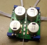
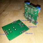
Here is my integrated fully differential module (4 layer design) for stereo balanced/unbalanced outputs (105/105D as 95 models). It can be used for multichannel stage too, for balanced/unbalanced outputs.
It use OPA1632 and it include TPS adjustable regulators for +/- rails of I/V and for final buffers stages. Optional/customizable filter footprints are provided on the bottom side.
An upgraded version is already in production.
BTW, I use the same large decoupling capacities approach, which bring only high quality results. ..
Attachments
Last edited:
Terry - this is still a bit above my head - but do I understand correctly that you are saying large caps at the DAC power rails are providing value only when they act to reduce noise from less-than-ideal regulators... And that such capacitance has less value if the regulator is designed to provide lower noise ?
The main issue Joe was focusing on was reduction of very low frequency ie; subsonic, noise by using super caps. So I was pointing out:
a/ These standard Oppo regulators produce substantial noise in this region and
b/ The supercaps can not really reduce this noise to any large degree due to the extremely low OP impedance of the regulator at low frequencies.
If subsonic noise in the region of 1Hz and lower is truly a major sonic issue then you are better off designing a regulator from the ground up that has very low noise in this area.
Whether the regulator is shunt or series pass doesn't make much difference to low frequency noise. To reduce the very low frequency noise to super low levels just requires very careful design and good understanding of the principals.
Terry
The main issue Joe was focusing on was reduction of very low frequency ie; subsonic, noise...
... and active versus passive? We know passive works, because we have tried it and not hard to hear a very positive result. Yet to try active and in theory should be better, I grant that, but... and what if the combination of both shines? Would not necessarily be a bad thing - whatever it takes to get the best sound.
Cheers, Joe
.
Joe,... and active versus passive? We know passive works, because we have tried it and not hard to hear a very positive result. Yet to try active and in theory should be better, I grant that, but... and what if the combination of both shines? Would not necessarily be a bad thing - whatever it takes to get the best sound.
Cheers, Joe
Your memory is not serving you well these days - scratching my head.
 LOL
LOL We discussed active versus passive over the phone. Any regulator will use feedback to achieve low OP Z, be it discrete or monolythic and as such both are 'active'.
Any capacitor at the OP will interact with either type of regulator in the same way affecting it's stability and phase margin. I'm not sure why you keep coming back to this analogy. Good marketing angle?
Both approaches are the same.
As an update on my regulator design:
I have been doing extensive research on LF noise sources, have identified the lowest noise references and now actually designed a discrete reference which has even lower LF noise. It's tricky because you are basically weighing up noise verses voltage stability. The discrete ref has worse voltage stability versus temperature but better LF noise specs.
I think in this case absolute stability is secondary to LF noise.
Having said all of the above - we still don't really know how important reduction of this LF noise is. There is no real scientific evaluation or measurement of LF noise (which is tricky) to correlate to listening tests.
T
Joe,
Your memory is not serving you well these days - scratching my head.
Me too.
 LOL
LOL We discussed active versus passive over the phone. Any regulator will use feedback to achieve low OP Z, be it discrete or monolythic and as such both are 'active'.
Nothing I said disagrees with that. They are both 'active' - agreed.
As an update on my regulator design:
I have been doing extensive research on LF noise sources, have identified the lowest noise references and now actually designed a discrete reference which has even lower LF noise. It's tricky because you are basically weighing up noise verses voltage stability. The discrete ref has worse voltage stability versus temperature but better LF noise specs.
On paper, as you say, the discrete Vref would then be better. I understand, drift is a lesser problem than noise - although drift needs to be rather slow... where to draw the line between the two, at what point does noise become drift, or should I say drift become noise, or...
I think in this case absolute stability is secondary to LF noise.
or... do they overlap? Are we talking about the fact we don't know exactly where the boundary is?
Any capacitor at the OP will interact with either type of regulator in the same way affecting it's stability and phase margin. I'm not sure why you keep coming back to this analogy. Good marketing angle?
Both approaches are the same.
Agreed, except on the fact that I never thought I was doing any marketing. Now my turn to scratch my head... again...
LOL Perhaps I was not as clear as I could be, language is always a limitation. We need to set the voltage (usually +3.3V) and that needs a reg. Always will. We already have a reg, so is the solution a better reg? I think you say yes, and I say why not? Hence my point was that either the solution (to a better end result) was to go 'active' in the sense we need what you are championing, a better reg. On the other hand, by saying 'passive' I was clearly meaning in context, along with the existing garden variety reg (no doubt inferior to yours, and I am not saying this cynically because I would certainly expect it to be) adding massive 'passive' capacitance. No marketing intended, just describing the two approaches.
But maybe, as we know we do need a cap (passive) there as well with an improved reg, usually stacked film, then also adding large amounts of capacitance may prove complimentary.
As it is, the improvement achieved is undeniable, even before we add your reg, that has already been achieved, but nobody is denying the possibility that your improved reg will not make something good even better.
Having said all of the above - we still don't really know how important reduction of this LF noise is. There is no real scientific evaluation or measurement of LF noise (which is tricky) to correlate to listening tests.
T
Ain't that the truth!!! And worse, there seem to be little intent or will to do exactly what you say. Tricky? Put it in the "too hard basket"? If there was a will, then a way would be found.
Cheers, Joe
.
Last edited:
Me too.
Nothing I said disagrees with that. They are both 'active' - agreed.
On paper, as you say, the discrete Vref would then be better. I understand, drift is a lesser problem than noise - although drift needs to be rather slow... where to draw the line between the two, at what point does noise become drift, or should I say drift become noise, or...
I am referring to voltage versus temperature stability. You can trim it to 3.3V at 25 deg but at 40 deg that 3.3 will change. So it's not random 'noise' drift, it's directly related to temp.
There are some super low noise V refs readily available but a/ they are pretty expensive b/ if temp stability is not super critical I can further improve on their LF noise spec.
Generally LF noise on references (and regs) is specced as V P-P for 0.1Hz to 10Hz.or... do they overlap? Are we talking about the fact we don't know exactly where the boundary is?
Only one way to find out!Perhaps I was not as clear as I could be, language is always a limitation. We need to set the voltage (usually +3.3V) and that needs a reg. Always will. We already have a reg, so is the solution a better reg?
At the frequencies of interest, ie; very low, the standard reg is as 'active' as any other regulator and has a very low OP Z.I think you say yes, and I say why not? Hence my point was that either the solution (to a better end result) was to go 'active' in the sense we need what you are championing, a better reg. On the other hand, by saying 'passive' I was clearly meaning in context, along with the existing garden variety reg (no doubt inferior to yours, and I am not saying this cynically because I would certainly expect it to be) adding massive 'passive' capacitance. No marketing intended, just describing the two approaches.
Having said that, has anyone here read the article in Jan's Linear Audio (V4?) testing regs. I believe most were some way from their spec sheets.
I would leave the caps the same and just change the reg. Rule 1 in mods is just change 1 thing at a time so you know what is causing effect.But maybe, as we know we do need a cap (passive) there as well with an improved reg, usually stacked film, then also adding large amounts of capacitance may prove complimentary.
I really should make a super low noise x 2000 (or so) amplifier so I can measure some of this stuff.As it is, the improvement achieved is undeniable, even before we add your reg, that has already been achieved, but nobody is denying the possibility that your improved reg will not make something good even better.
cheers
T
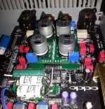
My complete (add on) modification for 95, 105/105D.
Not in picture the clock board, but it is installed too in this case. In the pictured I/V &Final buffer module, is not shown the shielding can over the bottom circuits area, as the special designed flat cable for differential connections on DAC`s outputs. The missing items are not arrived yet.
BTW, the post DAC signal processing module is actually to be equipped with 10000µ Nichicon caps.
Attachments
Last edited:
- Home
- Source & Line
- Digital Source
- Oppo's BDP105 - discussions, upgrading, mods...