anyone interested ? pcbs only
14x8cm
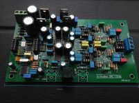
dual mono pcm1794A 132db
Upscaller 32 bit cs8421 - can be bypassed
receiver wm8805 - 24bit 192khz --- 50ps jitter
Output XLR and singl ended ,opamps + gain stage for XLR
XLR standart 3.16v using Toshiba sc1815
Center tapped transformer input
12-0-12 to 22-0-22
14x8cm
dual mono pcm1794A 132db
Upscaller 32 bit cs8421 - can be bypassed
receiver wm8805 - 24bit 192khz --- 50ps jitter
Output XLR and singl ended ,opamps + gain stage for XLR
XLR standart 3.16v using Toshiba sc1815
Center tapped transformer input
12-0-12 to 22-0-22
Attachments
S.houbed DAC revise 1.1
Hi
have some new ideas
-replace in IV the 4 caps that are in line with 2.2nF
-add a low pass filter before i/v if you want to use opamps like the Opa2277
with 0.8 slew rate LC low pass recommended
-also you can add 680pf + 2ohm in series from opamp neg input to GND
Hi
have some new ideas
-replace in IV the 4 caps that are in line with 2.2nF
-add a low pass filter before i/v if you want to use opamps like the Opa2277
with 0.8 slew rate LC low pass recommended
-also you can add 680pf + 2ohm in series from opamp neg input to GND
Last edited:
It has the resistor-cap to dump the high freq noise to ground(many of the builders omit that)
so it will be clean,its like using a transistor for supply noise filtering in analog circuitry
and LPF before preamp,usefull thing
It's no cleare where you put them. Could you be more precise ?
being a diy site and being a diyer, it really would be better if you didnt just pull the 132db performance spec directly from the pcm1794A datasheet and print it on the PCB; presumably deciding to print it on the PCB before youve even built it.... its bad enough when companies marketing departments do this.
the design is OK, but I doubt youve met the datasheet spec, thats usually a pretty hard task that involves a tighter SMD layout and several iterations. how about some real performance measurements?
the design is OK, but I doubt youve met the datasheet spec, thats usually a pretty hard task that involves a tighter SMD layout and several iterations. how about some real performance measurements?
Last edited:
being a diy site and being a diyer, it really would be better if you didnt just pull the 132db performance spec directly from the pcm1794A datasheet and print it on the PCB; presumably deciding to print it on the PCB before youve even built it.... its bad enough when companies marketing departments do this.
the design is OK, but I doubt youve met the datasheet spec, thats usually a pretty hard task that involves a tighter SMD layout and several iterations. how about some real performance measurements?
I agree with you, and , if you want say all the truth, even the data sheets have fake performance printed on.
I.E., the following link is a discussion where you can find out that the PCM1792 (almost the same of the 1794) has performance issues....
PCM1792 performance issues. - Audio Converters Forum - Audio Converters - TI E2E Community
Last edited:
you meassure yourself,i choosed the best in it and will try to improve it,i dont tend to get rich from this.
here some tweaks
add capacitor between i- and i+ will act as a LPF
Coupling Capacitor Calculator by V-Cap
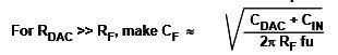
and the cap parallel to 195 ohm should be :
Rf is the 195 ohm resistor can be increased up to 400ohm to increase voltage if you want more from XLR,but it will limit The Q factor of the opamp gain stage
Voltage bigger --needs higher slew rate
with <5v you can go with 0.8v/us up to 25khz
here some tweaks
add capacitor between i- and i+ will act as a LPF
Coupling Capacitor Calculator by V-Cap
and the cap parallel to 195 ohm should be :
Rf is the 195 ohm resistor can be increased up to 400ohm to increase voltage if you want more from XLR,but it will limit The Q factor of the opamp gain stage
Voltage bigger --needs higher slew rate
with <5v you can go with 0.8v/us up to 25khz
Attachments
Last edited:
add capacitor between i- and i+ will act as a LPF
Thank you for your prompt answer.
I've also noticed some high frequence noise floor on the output of the PCM so in the layout of my PCB I put the place for a small polyester SMD capacitor between the i+ and i-. But actually it's a 20Mhz noise of few mV so i decided to not mount them.
Do you think this kind of noise can be a problem for the next stages ? Have you experience that the capacitor make any difference at listening test?
Last edited:
you meassure yourself,i choosed the best in it and will try to improve it,i dont tend to get rich from this.
here some tweaks
add capacitor between i- and i+ will act as a LPF
Coupling Capacitor Calculator by V-Cap
and the cap parallel to 195 ohm should be :
Rf is the 195 ohm resistor can be increased up to 400ohm to increase voltage if you want more from XLR,but it will limit The Q factor of the opamp gain stage
Voltage bigger --needs higher slew rate
with <5v you can go with 0.8v/us up to 25khz
all good, I just think its unnecessary. not suggesting you will get rich from this, just that it would be better if you didnt print false specifications on the PCB and on the thread title when you obviously dont know its actual performance.
all good, I just think its unnecessary. not suggesting you will get rich from this, just that it would be better if you didnt print false specifications on the PCB and on the thread title when you obviously dont know its actual performance.
The message was clear the first time you wrote it. Please let him describe more accurately his project and don't polemize on silly details.
")
when someone makes a comment like this, its not clear to me the motivation for what I said was understood by HIM, obviously you understood it. I didnt repeat/clarify it for you....you meassure yourself,i choosed the best in it and will try to improve it,i dont tend to get rich from this.
it does the design a disservice as well, since it wont happen to meet the number
Last edited:
New,out low pass S.houbed
Hi
new improvement
valid for Active filter opamp
Calculated for opa2134 cuttof at 25.3khz
increase Q factor very Much > 10 times
1.replacethe first 6.8k with 250R(4times amp or 12db gain) to 1k(No gain-double Q factor)
2.replace the rest of 6.8k with 1k
3.replace the 102k and 7k5 use only one 1k or two in parallel total 1k
4.filter capacitor 172pf(its the one on the opamp end from the 2 res in parallel)
5.replace 1n with 230nF
if need other opamps claculate here:
(Sample)Multiple Feedback Low-pass Filter Design Tool - Result -
for caps if one is 220pf the other one is 180n
AND finally 180pf and 220n (220p and 180n) -you get same 25291.38Hz
you can even make it floating thats 2x220n
Last edited:
- Status
- This old topic is closed. If you want to reopen this topic, contact a moderator using the "Report Post" button.
- Home
- Source & Line
- Digital Source
- S.houBed DAC 132db Dual MONO pcm1794