Hi there,
Two days ago I had a very intresting listening experience with some of my
friends. We compared my CD player (Denon DCD-1450AR) to a really old
Phillips (I do not know its type number, but it had metal loading mechanism
and 14 bit D/A converter) with tube output stage (Of course it is a tunning
made by a respected Hungarian fellow.). The Phillips easily surpassed the
Denon...Since I already owned three CD players and the Denon is the only one
wich has not been modified yet my thoughts were next day that the time is
now.
What I intend to do:
- change those nasty NE5532p opamps
- change some of the capacitors (values/types)
- include a discrete output stage (really simple circuit, but it always
showed improvements when I used them)
- change the 78xx, 79xx supply regulators used in the analogue stages to
discrete ones (there is room enough for an additional pcb)
- I plan to run the regulators and the output stage from a dedicated
transformator
- remove the muting transistors
- bypass the inbuild volume controll (this player has a brother with
variable and fixed output as well, so I assume it can be done.)
However, before trying and then hoping that everything will go well I ask
you about your opinons. (It is mainly because this player isn't so bad at
all and I certainly do not want to ruin it...)
So here are my questions:
- what are your suggestions about the NE5532p replacement?
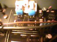
- there are some kind of high value (I assume) capacitors used in the
analogue section which I don't know and furthermore I can't read their
values. I made a picture of them with my palm device. They have writings on
them like 102J/100. The 100 is written below the 102J. Fisrt I thought that
the 100 means 100nF, but when I checked the other ones I found in the upper
line values like 101, 102 and 271 always with a "J" after them and always
with a "100" below them. So I don't know...
Thank you for your help.
Cheers:
Bt
P.S:: I try to look after the service manual because it would help a lot,
but if someone has it then please post here...
Two days ago I had a very intresting listening experience with some of my
friends. We compared my CD player (Denon DCD-1450AR) to a really old
Phillips (I do not know its type number, but it had metal loading mechanism
and 14 bit D/A converter) with tube output stage (Of course it is a tunning
made by a respected Hungarian fellow.). The Phillips easily surpassed the
Denon...Since I already owned three CD players and the Denon is the only one
wich has not been modified yet my thoughts were next day that the time is
now.
What I intend to do:
- change those nasty NE5532p opamps
- change some of the capacitors (values/types)
- include a discrete output stage (really simple circuit, but it always
showed improvements when I used them)
- change the 78xx, 79xx supply regulators used in the analogue stages to
discrete ones (there is room enough for an additional pcb)
- I plan to run the regulators and the output stage from a dedicated
transformator
- remove the muting transistors
- bypass the inbuild volume controll (this player has a brother with
variable and fixed output as well, so I assume it can be done.)
However, before trying and then hoping that everything will go well I ask
you about your opinons. (It is mainly because this player isn't so bad at
all and I certainly do not want to ruin it...)
So here are my questions:
- what are your suggestions about the NE5532p replacement?
- there are some kind of high value (I assume) capacitors used in the
analogue section which I don't know and furthermore I can't read their
values. I made a picture of them with my palm device. They have writings on
them like 102J/100. The 100 is written below the 102J. Fisrt I thought that
the 100 means 100nF, but when I checked the other ones I found in the upper
line values like 101, 102 and 271 always with a "J" after them and always
with a "100" below them. So I don't know...
Thank you for your help.
Cheers:
Bt
P.S:: I try to look after the service manual because it would help a lot,
but if someone has it then please post here...
Attachments
Hi again,
I tried to find out a few things about the topic during the past days. First I realized that I asked a question discussed here more than enough time - namely the replace possibilites of NE5532. I read most of the topics but at the end a completly other solution came to my mind. No matter how hard I tried (and I can tell you that I can be quite stubborn sometimes) I couldn't lay my hands on the service manual of the player. Of course I spent a half an hour just peering the PCB but I wasn't convenienced about wheter this project would turn out positively without knowing what I am dealing with. But then came the idea to make a completely new ouput stage�This player utilizes a BB PCM1702 chip, which is not the best, but on the other hand well known and there are a couple of DIY projects dealing with it. So after a search I found Jukka Tolonen's solution as an easy enough and promising possibilty.
http://koti.mbnet.fi/siliconf/JukkaTolonen/projects/jt-dac_no.3/pix/jtdac3b3.gif
However, during a long train journey a decided to alter the shematic a bit. Since the second opamp is used just for buffering I think that a simple emitter follower can overtake its task. I plan to do this with a MAT04 per channel with the 4 bjts connected parallel. It is mainly because I have two MAT04s at home and because I really like simple single-ended things. (They wouldn't be noisy with batteries, that is sure.) I have also decided to power the output stage from 9 volt batteries. However I don't know wheter I should use a capacitor on the PCB or not. As I can recall I read somewhere that capacitors are faster then batteries and therefore they have to be used for this reason but I am not sure...Any hint?
As a side project I will also desing a simple logical network for powering up and down this stage because I do not wish to change batteries weekly...My though are that the output stage will be powered up when:
- the player is turned on. (If nothing happens 5 minutes after this event, the batteries are going to be disconnected.)
- the eject button is pushed (With the same conditions as written above.)
- the disc is rotating (And again five minutes after the rotation stopped.)
For this I plan to monitor the voltages of the electric motors of the eject and disc playing mechanism and also the power condition for the first criterion. The task needs logical OR gates and some timing solution. Any suggestion about this? Also, I imagine to disconnect the batteries with some kind of relay. Again, suggestion about the pitfalls would be appreciated.
And a last question. Where can I get inductors of the needed values? I live in Hungary and it seems to be a bit difficult to get them (to be more precise till know I haven't found any source for them). I can use my card to purchase them over the net but I then I need a place which is willing to ship this small quantity. Any idea?
Cheers:
Bt
- Status
- This old topic is closed. If you want to reopen this topic, contact a moderator using the "Report Post" button.