Since the beginning of my quest to design a good dac around the pcm1794, i had some doubts about some characteristics of this chip.
And it seems that is a lot of contradictory info in this forum about them. some of my doubts are the output impedance, the distortion and noise of using the dac in single end VS differential, and the influence of the input impedance of the I/V converter.
hope that with your help we can shed some light on the subject.
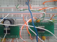
This tests were made with pcm1794 and dir9001 in a breadboard.
I use the line input and spdif out of the sound card (emu1212m), for distortion measurements.
And it seems that is a lot of contradictory info in this forum about them. some of my doubts are the output impedance, the distortion and noise of using the dac in single end VS differential, and the influence of the input impedance of the I/V converter.
hope that with your help we can shed some light on the subject.
This tests were made with pcm1794 and dir9001 in a breadboard.
I use the line input and spdif out of the sound card (emu1212m), for distortion measurements.
Attachments
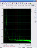
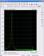
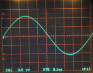
this first test is about the distortion level caused by the impedance at the output of the pcm1794. There is the widespread idea that the lower the output impedance seen by the dac the better. but how low is enough?
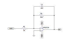
this test was made by connecting the pin IoutL+ to a classical ampop I/V converter (opa2134) with a resistor of 50 , 100, and 150 ohms in serie.
the pin IoutL- was connected to ground.
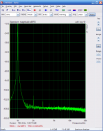
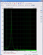
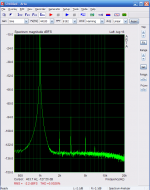
the first picture is with no resistence in serie, the 2º is with 100 ohms (r1) , the 3º is with 150 ohms. the picture with 50 ohms is ommited because there is no visible difference between the one that has no serie resistence.
this test was made by connecting the pin IoutL+ to a classical ampop I/V converter (opa2134) with a resistor of 50 , 100, and 150 ohms in serie.
the pin IoutL- was connected to ground.
the first picture is with no resistence in serie, the 2º is with 100 ohms (r1) , the 3º is with 150 ohms. the picture with 50 ohms is ommited because there is no visible difference between the one that has no serie resistence.
Attachments
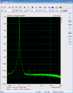
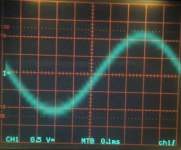
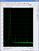
this test was made by connecting the pin IoutL+ with a resistor of 50 ohms to ground and measure the distortion at the pin IoutL+.
The pin IoutL- was connected to ground.
The distortion and noise are real low. (0,0005%) the output level of the dac was -1 dbFS.
The pin IoutL- was connected to ground.
The distortion and noise are real low. (0,0005%) the output level of the dac was -1 dbFS.
Attachments
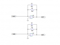
One thing that is important in the case you opt by using this type of I/V converter is to choose a high quality capacitor for C1 (polipropilene or C0G ceramic). this pictures are the distortion of using a polipropilene (MKP) capacitor or a bad quality capacitor.
this test use a differencial I/V converter.
this test use a differencial I/V converter.
Attachments
summarizing:
There is no problem using a I/V converter with a input impedance of 50 ohms or lower.
There is not a great difference between differencial or single end.
Ween using a passive resistence as a I/V converter connect the IoutL- and IoutR- pins to the ground.
I will let you digest this information for now.
If you have any doubts or questions please feel free to ask.
Sergio, thanks for providing this battery of very interesting test results. Your 150R I/V THD figure of 0.0022% exactly matches my own test result with 150R ") , except that my DAC's output is completely passive. I don't utilize any gain stage for normalizing signal levels to 2VRMS prior to sending them to the linestage unit for any needed gain.
, except that my DAC's output is completely passive. I don't utilize any gain stage for normalizing signal levels to 2VRMS prior to sending them to the linestage unit for any needed gain.
What I/V resistance value was utilized in the differential mode test?
, except that my DAC's output is completely passive. I don't utilize any gain stage for normalizing signal levels to 2VRMS prior to sending them to the linestage unit for any needed gain.What I/V resistance value was utilized in the differential mode test?
Last edited:
Thank Ken, there is even more.
completely passive !!! how ? do you use a transformer ?
In post #4 i use 1k ohm , this post is just to warn about the use of bad quality capacitor in the feedback path, that can have a huge impact in the linearity.
the best results in balanced mode was 0.00022%, that is also the limit of the emu1212m.
But breadboard is not the most perfect environment for sensible audio equipment ( a good ground is very important to keep the distortion and noise values low).
In this test i use 510 ohms and no capacitor.
Attachments
output impedance of the PCM1794
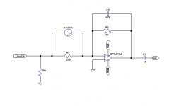
One important value is the output impedance of the PCM1794.
Some say it is 2k ohms, others say is less than 1K ohms, Ti says is 2 Mega ohms.
By my experience it is more than 100K ohms .
I have use the following circuit to come up to this result.
first i have use a 10k in "Rx", and measure the output with the switch close and then with the switch open, then i repeat the same procedure with 20k , 100k and at last without Rx. the results are this:
switch - close - open
10k - 21.16db - 21.33db
20k - 21.16db - 21.24db
100k - 21.16db - 21.18db
Zero - 21.16db - 21.16db
As there is no diference in output voltage when there is no resistence in parallel with the output of the dac, i assume the impedance is greater than 100k , because when we use 100k, we can sense a difference betwen the switch is close and when is open.
I have try this with -1db , -21db , -43db ,always with the same result.
It is very difficult to measure better than this, because of the temperature and noise. the 2 Mega ohms that Texas presents is plausible but i can not measure that.
Attachments
Thank Ken,
....completely passive !!! how ? do you use a transformer ?..... In this test i use 510 ohms and no capacitor.
I simply have an 150R I/V resistor connected from each output pin of the PCM1794A to ground. The resulting signal is centered on a D.C. voltage offset of +930mV due to the DAC's output bias current flowing through the I/V resistor to ground. The junction of each DAC output pin and it's I/V resistor is then A.C. coupled to it's respective output jack via a capacitor. The output impedance will be no greater than the value of the I/V resistor, which in my case is 150 ohms. The fullscale A.C. signal amplitude is just over 400mVRMS, single-ended. My linestage has single-ended inputs. Which means that I require only 14dB of gain to obtain a standard 2VRMS level for driving my power amp. My JFET linestage has sufficient gain for this purpose, so I'm able to eliminate any intervening active circuitry between the PCM1794A and the output jack.
Nickle or amorphous steel core transformers tend to be quite expensive, are very sensitive to D.C. offset at their primary windings, and are best driven by very low impedance sources. In addition, utilizing a step-up (or even a one-to-one ratio transformer) will rapidly increase the signal output impedance seen from the jack. For example, using 150R I/V resistors, the differential source impedance as seen by a transformer's primary is 300 ohms. If the step-up ratio is 1:2, then the signal output impedance presented by the secondary will be, 300 ohms X 4 = 1.2K ohms, a figure excludes the effect of both the primary and secondary winding resistances. For those reasons, I opted for capcitor coupling over transformer coupling.
Can you please detail the 510 ohm I/V resistor placement in your differential test circuit having the low 0.00022% THD?
Last edited:
Interesting thread, I use two PCM1794A in mono mode, one per channel with output currents summed into 2 ohm resistors for I/V conversion, from there the differential output goes into Sowter 9545 "I/V conversion" transformers, (note in my design the conversion is done by a pair of 2 ohm resistors per channel) and is then further amplified by a choke loaded 5842. Seems to work pretty well, FS output is about 3Vrms which was my target.
Nice to see that the linearity of the dac is still very good out to 50 ohms or so, information on performance of resistive I/V conversion and compliance voltage limits of the 1794A current outputs is not readily available.
Thanks for sharing this information!
Nice to see that the linearity of the dac is still very good out to 50 ohms or so, information on performance of resistive I/V conversion and compliance voltage limits of the 1794A current outputs is not readily available.
Thanks for sharing this information!
Ok Ken. i us thinking that you meant that you manage to get 2vrms out of the PCM1794.
One thing that you may try is to connect the negative output of the 1794 to the ground and only use the 150 resistor in the positive output. I dont have made this test with 150 ohms but i did with 50 ,100 , and 200 ohms and when the negative is connected to ground the pair harmonics increase and the odd harmonics decrease.
the first image are with a 100 ohms in IoutL+ and Iout- connected to ground
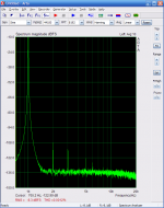
the second image are with 100 ohms in IoutL+ and 100 ohms IoutL-
the reading was made in the IoutL+ to both tests
One thing that you may try is to connect the negative output of the 1794 to the ground and only use the 150 resistor in the positive output. I dont have made this test with 150 ohms but i did with 50 ,100 , and 200 ohms and when the negative is connected to ground the pair harmonics increase and the odd harmonics decrease.
the first image are with a 100 ohms in IoutL+ and Iout- connected to ground
the second image are with 100 ohms in IoutL+ and 100 ohms IoutL-
the reading was made in the IoutL+ to both tests
Attachments

Can you please detail the 510 ohm I/V resistor placement in your differential test circuit having the low 0.00022% THD?
That was a test to see the impact that ground have in distortion, i was changing the ground wires and test the distortion, i dont think that have 510 ohms or 1k made great diference, the low distortion numbers are mainly due to better ground in this test. A proper PCB is a must in this type of circuitry.
Attachments
Ok Ken. i us thinking that you meant that you manage to get 2vrms out of the PCM1794.
One thing that you may try is to connect the negative output of the 1794 to the ground and only use the 150 resistor in the positive output. I dont have made this test with 150 ohms but i did with 50 ,100 , and 200 ohms and when the negative is connected to ground the pair harmonics increase and the odd harmonics decrease.
the first image are with a 100 ohms in IoutL+ and Iout- connected to ground
the second image are with 100 ohms in IoutL+ and 100 ohms IoutL-
the reading was made in the IoutL+ to both tests
This result is really interesting! Although I'm only using the output of one phase, I currently have the unused output phase connected to another 150R resistor. I definitely will try connecting the unused output directly to ground.
That was a test to see the impact that ground have in distortion...
Okay, I see now. The differential outputs are driving conventional virtual ground input I/V stages.
Interesting thread, I use two PCM1794A in mono mode, one per channel with output currents summed into 2 ohm resistors for I/V conversion, from there the differential output goes into Sowter 9545 "I/V conversion" transformers, (note in my design the conversion is done by a pair of 2 ohm resistors per channel) and is then further amplified by a choke loaded 5842. Seems to work pretty well, FS output is about 3Vrms which was my target.
Hi KevinKr,
Tube guys love their iron.
I like transformers too , but i think i don´t need one in that position, i have curiosity to try , but a good transformer is expensive , and i no longer have the patience to build one, in the past i have build a simple machine to wind some audio transformers, i have made some with nice specs with 8 interleaved for low leakage inductance, i already have a lot of C cores and magnet wire.
Made a mistake and connect the right output of the PCM1794 to the +15 volts, now the dac get hot very fast and there is no signal in the right but the left output still works.when the temperature of the dac rises the distortion also rises.
I have two more pcm1794, but i will not sacrifice other in the breadboard.
I have test the distortion in 96khz and it is higher than 44,1Khz but i forget to take a picture.
<snip>
I have test the distortion in 96khz and it is higher than 44,1Khz but i forget to take a picture.
And still higher at 192kHz..
Hi KevinKr,
Tube guys love their iron.
I like transformers too , but i think i don´t need one in that position, i have curiosity to try , but a good transformer is expensive , and i no longer have the patience to build one, in the past i have build a simple machine to wind some audio transformers, i have made some with nice specs with 8 interleaved for low leakage inductance, i already have a lot of C cores and magnet wire.
Yeah, they were expensive and had to be shipped from the UK, they do provide relatively effective low pass filtering and the electro-static shielding between the primary and secondary apparently kills a lot of HF rubbish, looks a lot cleaner than it did before. I'm pleased with the overall implementation, it sounds significantly better (better imaging, more low level detail even at 16/44) than the THS4130 it replaced.. Detailed measurements still to be performed..
- Status
- This old topic is closed. If you want to reopen this topic, contact a moderator using the "Report Post" button.
- Home
- Source & Line
- Digital Source
- Testing the pcm1794