This is question for jwb. I used his schema to build nice DAC with mosfet line driver output stage. Everything is OK but that output. Circuit built according to original schema. Weird things at least for me: power supply gives -/+ 14v but after it's connected to the circuit I measured at connector +14V and only -3.2V. Voltage between base and emitter of each transistor is at the level of 0.6V. Voltage accross D2 is 2.4V and 0.74V at D1. In other channel D2 has 2.16 and D1 0.97V.
Tried to increase supply voltage but no changes. The most terryfing is at the source of mosfet (output). I get 4 different voltages for +/- left and right. From 2.5V to 10V
Where should I start to fix that problem? Checked already connections - looks OK. I tried to match all components (R,C). What about the LEDs ? What voltage should they be? Need help, please .
Attachments
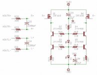
I should have mentioned that in my first post but from the circuit Rev B I took only output stage for cs43122. The chip DAC and receiver are placed on separate PCB of my own design and they work perfectly They have also different power supply than output stage.
1.I just wonder if I put correct LEDs 3.5V. Maybe they drain too much - I'm new in electronics field so for me everything is possible at least for now.
2.Maybe I damaged by solder heat some mosfets or transistors. How sensitive are they ?
3.What could be the reason for 10V output on one mosfet and 2.5V for the other.
Me stupid use bad, bad power supply. After 2 hours of checking everything 3 times step by step I came to conclusion that circuit is perfect so .... I took two 9V batteries, connected them to the circuit and ...  holy lord, it works.
So simple too difficult to find.
Thanks JWB for your time.
holy lord, it works. So simple too difficult to find.
Thanks JWB for your time.


- Status
- This old topic is closed. If you want to reopen this topic, contact a moderator using the "Report Post" button.